4 Units Description
4-4
Precautions:
1. Make sure that every gap between two panels is uniform and the sampling and
mixing holes in panel 2 aim at the holes in reaction disk correspondingly.
2. The mounting and dismounting of the table panel should follow the order
mentioned above. That is, when dismounting, the procedure should follow table
1 to panel2 to panel3. Mouting procedure should follow the reverse.
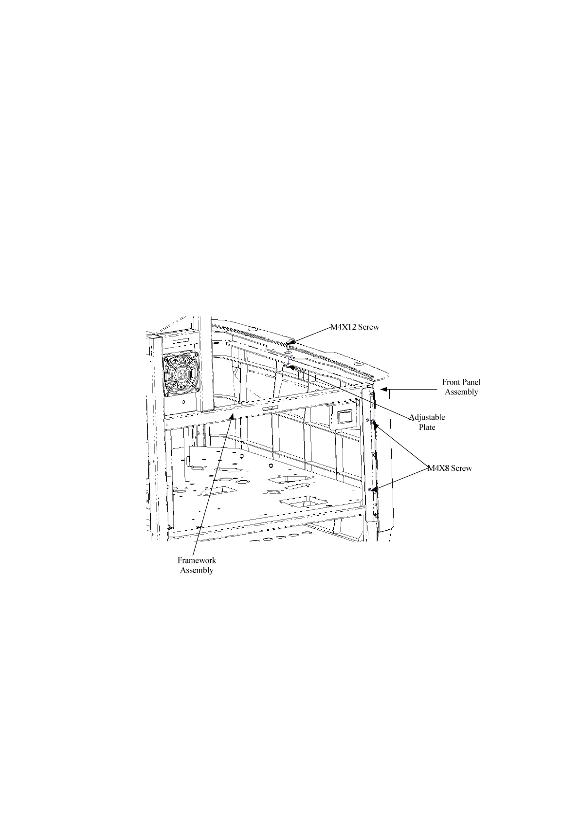
4.1.2.3 Dismounting/Mounting Front Panel Assembly
The procedures are shown as follows.
a. Remove table panel, left panel and right panel.
b. Loosen the fastening screws between the panel assembly and framework
assembly (see
Figure 4-4
).
c. When mounting them, reverse steps described above.
Figure 4-4 Removing Front Panel
4.1.2.4 Dismounting/Mounting Upright Panel and Top Panel
The dismounting/mounting procedures are described as follows.
a. After removing the table panel, loosen all the screws in upright panel and
remove the upright panel. See Figure 4-5.
b. After removing the left panel assembly and right panel assembly, loosen the
three screws on the back of top panel and remove the top panel.
c. To mount them, follow the sequence of top panel, upright panel, left and right
panel.