EasyManuals Logo

Mindray MX7 Service Manual

Mindray MX7
292 pages
To Next Page IconTo Next Page
To Previous Page IconTo Previous Page
Page #234 background imageLoading...
Page #234 background image
Part II General Information
Structure and Assembly/Disassembly 217
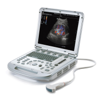
2. Remove the output control board.
Remove the 2-pin plug from the board, and then the two interconnection cable terminals (8-pin and
10-pin). Cut the cable tie using the cable cutter, remove the two M3X8 cross recessed panhead
screws for fixing the board, and take off the output control board.
5.3.12 Caster
Lock the four casters of the trolley and put down the trolley. Insert a custom hex wrench into the gap
between the caster and the base, remove the nut for fixing the caster, and take off the caster.
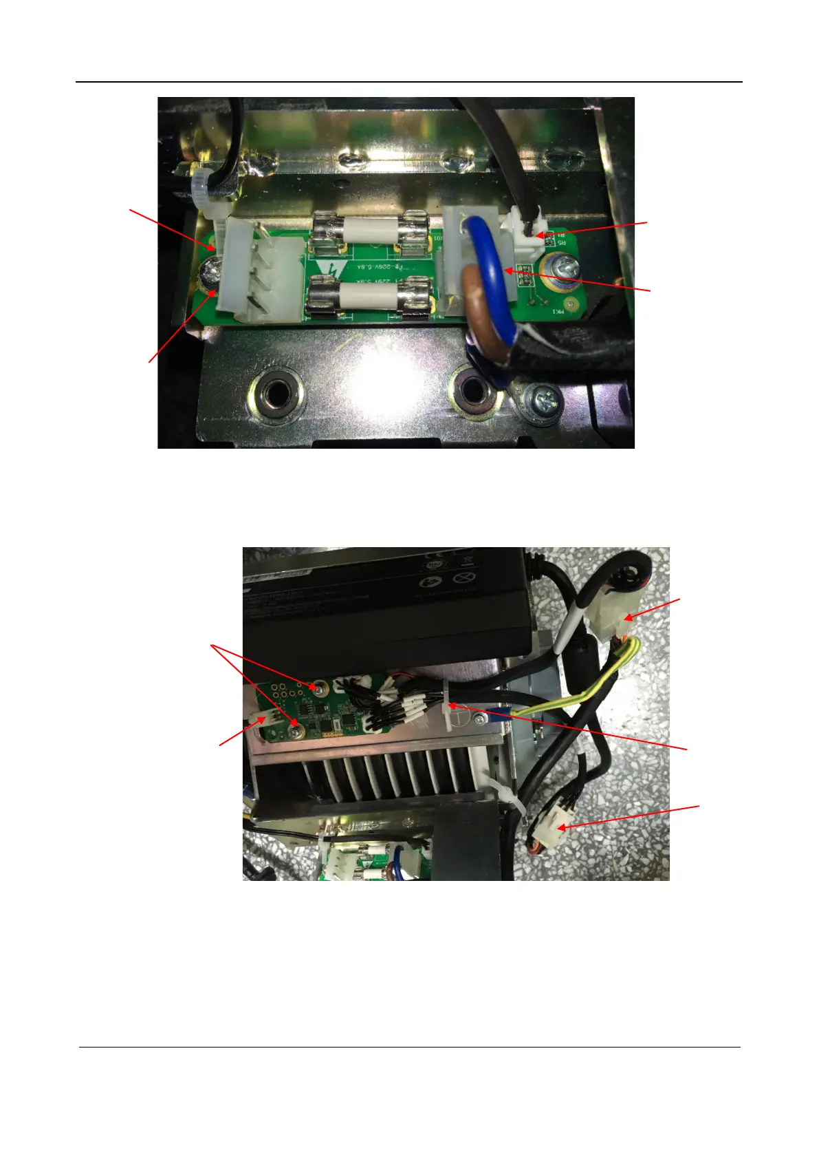
Protection and
indicator board
M3X8 cross
recessed panhead
screw (2 pcs)
2-pin plug
4-pin plug
8-pin plug
4-pin plug
Cable tie 2-pin plug
M3X8 cross
recessed panhead
screw (2 pcs)

Table of Contents

Other manuals for Mindray MX7

Questions and Answers:

Question and Answer IconNeed help?

Do you have a question about the Mindray MX7 and is the answer not in the manual?

Mindray MX7 Specifications

General IconGeneral
Display Size15.6 inches
Transducer Ports3
PortabilityPortable
TypeUltrasound System
Display TypeLCD
Battery Life120 min
Imaging ModesB, M, Color Doppler, Power Doppler, Pulsed Wave Doppler
ConnectivityWi-Fi, Ethernet, USB
ApplicationsVascular, Cardiology, OB/GYN, Urology
Probe Connectors3
Operating SystemWindows

Related product manuals