6
3. MV&TVe alarm off icon
4. Physiological alarm area
5. Apnea alarm off icon
6. Alarm silence icon area
7. System time
8. Technical alarm area
9. Power supply state icon area
Displays power source or battery icon. The icon
is displayed when
the anesthesia machine is powered by AC power source. The battery icon
is displayed when the anesthesia machine is battery powered to indicate
battery capacity.
10.[Vent Mode] shortcut key
Used to select mechanical ventilation mode.
11.[Alarm Setup] shortcut key
Used to change the alarm settings for the anesthetic ventilator, gas module
or BIS module.
12.[Screens] shortcut key
Used to set user screen.
13.[User Setup] shortcut key
Used to change the settings for TV compensation, O2 monitoring source,
gas module, BIS module, screen, sound etc.
14.[Maintenance] shortcut key
Used to perform leak test, calibrate O2 sensor and fl ow sensor, view trend
graph, trend table and alarm logbook, and set language, system time,
pressure unit, IP address etc.
15. Timer Setup shortcut key
16. Parameter Setup shortcut keys area
Used to set the parameters related to mechanical ventilation mode. Shortcut
keys arrangement is subject to specifi c mechanical ventilation mode.
17. System prompt message area
18. Parameter & graph area
Displays the parameters, waveforms, spirometry loops, or electronic
fl owmeter graphs which the anesthetic ventilator, gas module, or BIS module
monitors. Different types of screens are displayed based on the actual
system confi guration or screen layout settings.
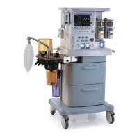
Display Screen
 Loading...

