F3 Service Manual
Page 28
c. Electronics Pack Circuit Boards
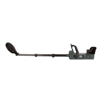
The F3 detectors electronics pack contains circuit boards that control power
supplies, transmit, receive and microprocessors. The electronics pack is an
LRU (Line Replaceable Unit).
The F3 circuit boards inside the electronics pack have shorting links (switches)
that are used to configure the detector during manufacturing. The shorting links
can be adjust to configure the electronics pack for an F3 or an F3L (with LEDs).
The F3 detector will have a threshold confidence tone or a heartbeat confidence
tone depending on the adjustment of the shorting links on the printed circuit
board.
Minelab supply electronics pack LRUs (Line Replaceable Unit) for the F3, F3L.
The electronics pack LRUs are assembled and tested in Minelab’s factory.
Provided that the correct electronics pack is used there is no requirement to
open the electronics pack.
d. Electronics Pack Compatibility
An F3 electronics pack can only be used on an F3 detector and similarly, an
F3L electronics pack can only be used on an F3L detector.
It is possible to open the electronics pack and convert an F3 electronics pack
to F3L electronics pack and likewise convert an F3L electronics pack to F3
electronics pack.
e. To Open the Electronics Pack:
Remove the electronics pack from the detector, refer to section 4.3.a To remove
the electronics pack.
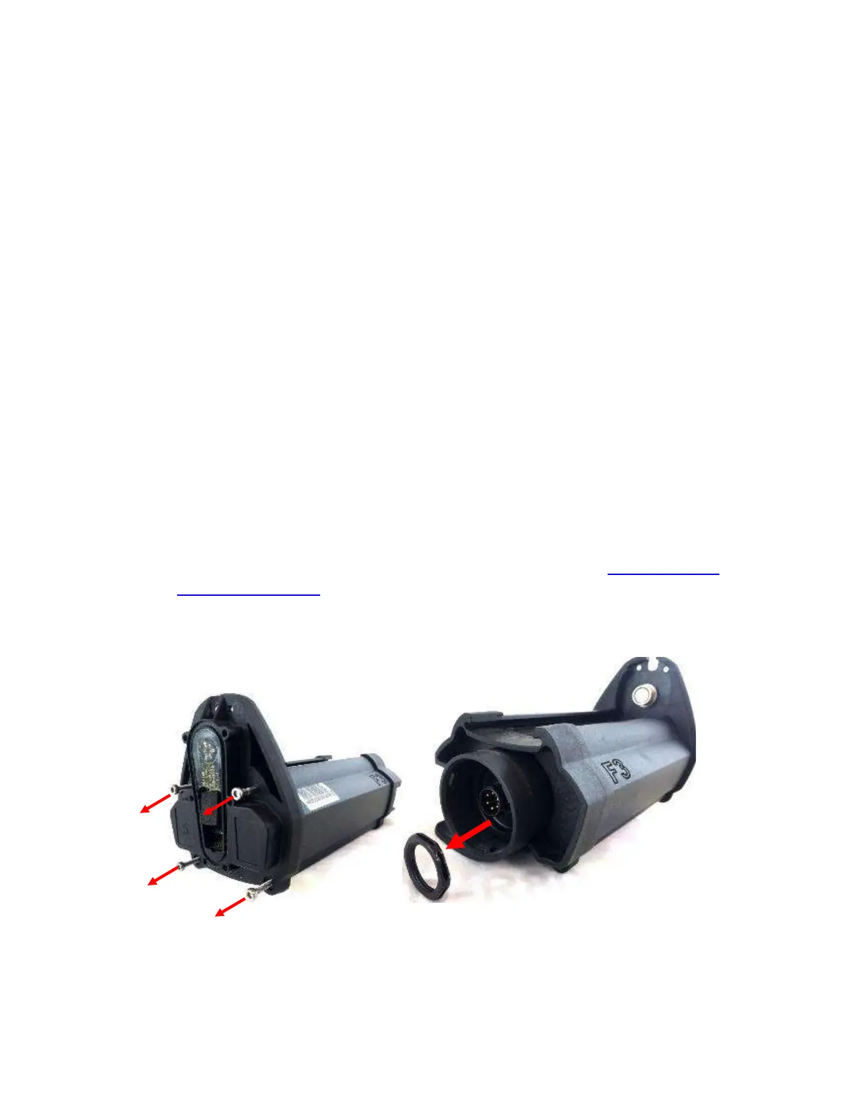
Remove four screws from the bulkhead of the electronics pack, as shown in
Figure 19.
Figure 19: Opening the Electronics Pack
Remove the 7/8 in battery connector mounting nut, as shown in Figure 19.
Remove the battery connector locking mechanism, as shown in Figure 20.
 Loading...