F3 Service Manual
Page 29
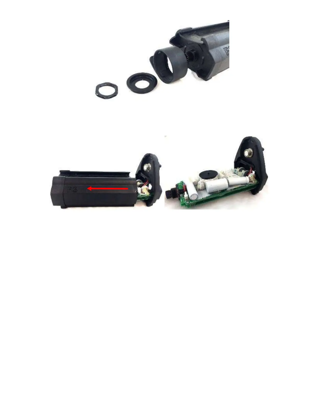
Figure 20: Removing battery connector locking mechanism.
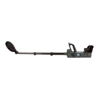
Slide the electronics pack housing backward exposing the circuit boards.
Figure 21: Removing the Electronics Pack housing.
The circuit boards and internal components of the electronics pack can now be
checked and the configuration links (switches) can be adjusted or checked.
The top circuit board (ps/tx pcb) with the larger components is the power
supplies and transmitter, the bottom circuit board (controller pcb) has the
microprocessors and signal processing circuitry.
Identify and check the configuration links on the micro pcb, refer to Figure 22.
 Loading...