4
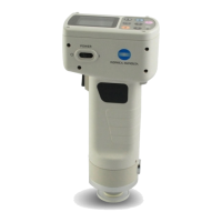
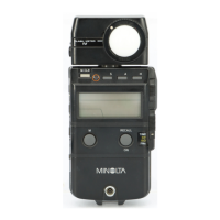
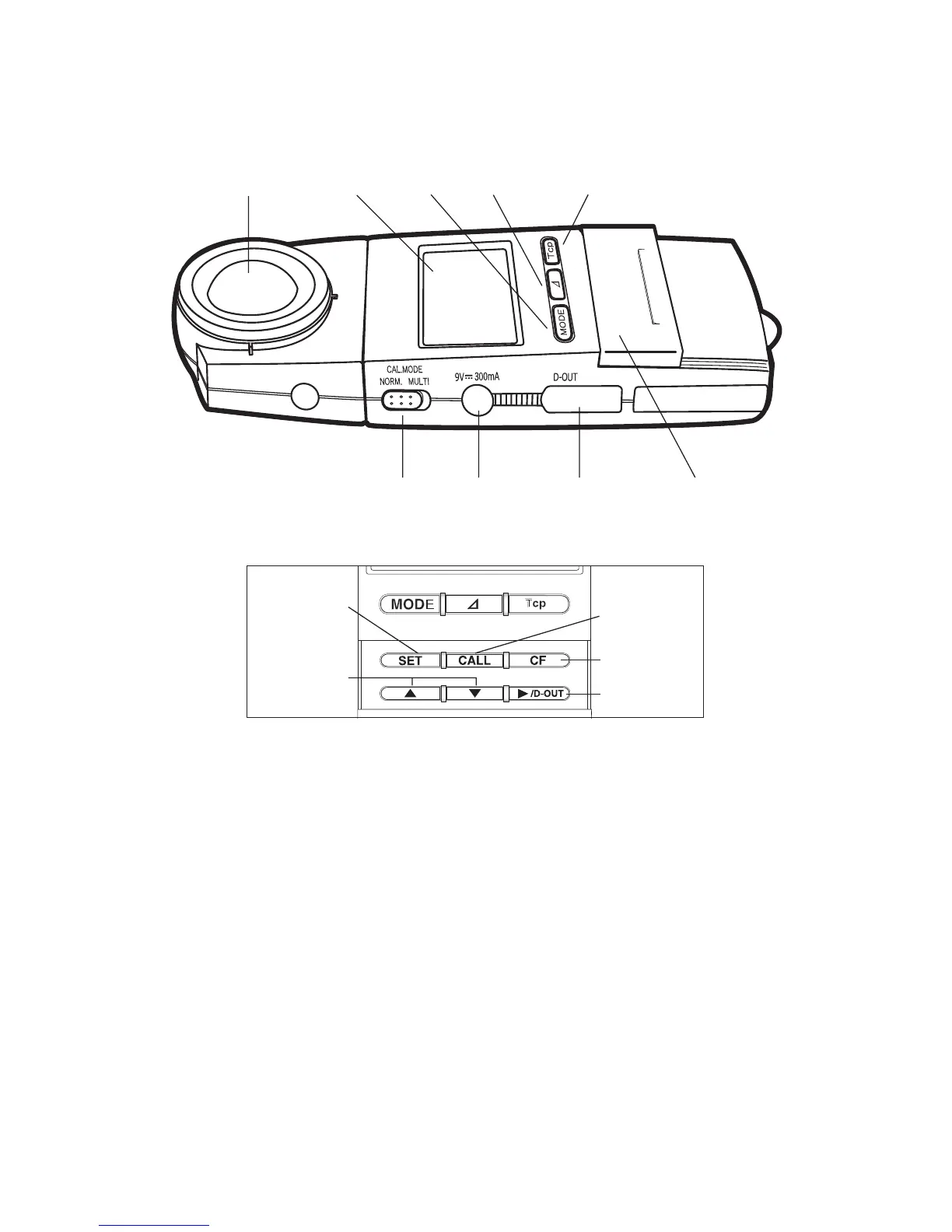
Names and Functions of Parts
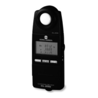
CL-200
1 Receptor Window
2 Display
Mode selector keys
3 [MODE] key...................... Sets the instrument into color measurement mode,
and switches the color coordinates.
4 [
∆] key .............................. Sets the instrument into color-difference measurement
mode, and switches the color-difference display.
5 [Tcp] key .......................... Selects color-temperature measurement/display
mode.
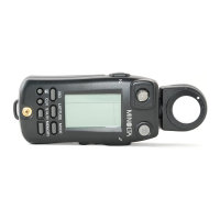
6 CAL MODE switch .......................... Selects the calibration mode: either NORMAL or
MULTI.
7 AC adapter jack .............................. Connects to an optional AC adapter AC-A10 (AC-
A10N in North America).
8 Digital output terminal .................... Outputs measurement data to a computer, printer, or
other peripheral.
1 234 5
67 8 9
(▲ When the slide cover is open)
0
A
D
C
B