12
General
The installation must be carried out in accordance with these instructions, and must
be conducted by designated, qualifi ed and competent personnel.
The installation must comply with the “Water Supply Regulations 1999 (Water Fittings)”
or any particular regulations and practices as specifi ed by the local water company
or water undertakers.
Note! Make sure that all site requirements correspond to the information given
in section: “Specifi cations.” For further details on Type 2 valves refer to supply
conditions in section: “Type 2 Valves.”
1. The Mixer must not be installed in an area where it may freeze.
2. For stud partitions, alternative fi xings may be required.
3. Isolating valves must be installed close to the Shower for ease of
maintenance.
4. Pipework must be rigidly supported. Avoid any strain on the connections.
5. Pipework dead-legs should be kept to a minimum.
6. Supply pipework layout should be arranged to minimise the effect of any other
outlet draw off upon the dynamic pressures at the Shower inlets, e.g. fl ushing
toilet. This is particularly important for gravity fed installations.
7. Inlet and outlet threaded joint connections
should be made with PTFE tape or liquid
sealant. Do not use oil-based, non-setting
joint compounds.
8. To eliminate pipe debris, it is essential
that supply pipes are thoroughly fl ushed
through before fi nal connection.
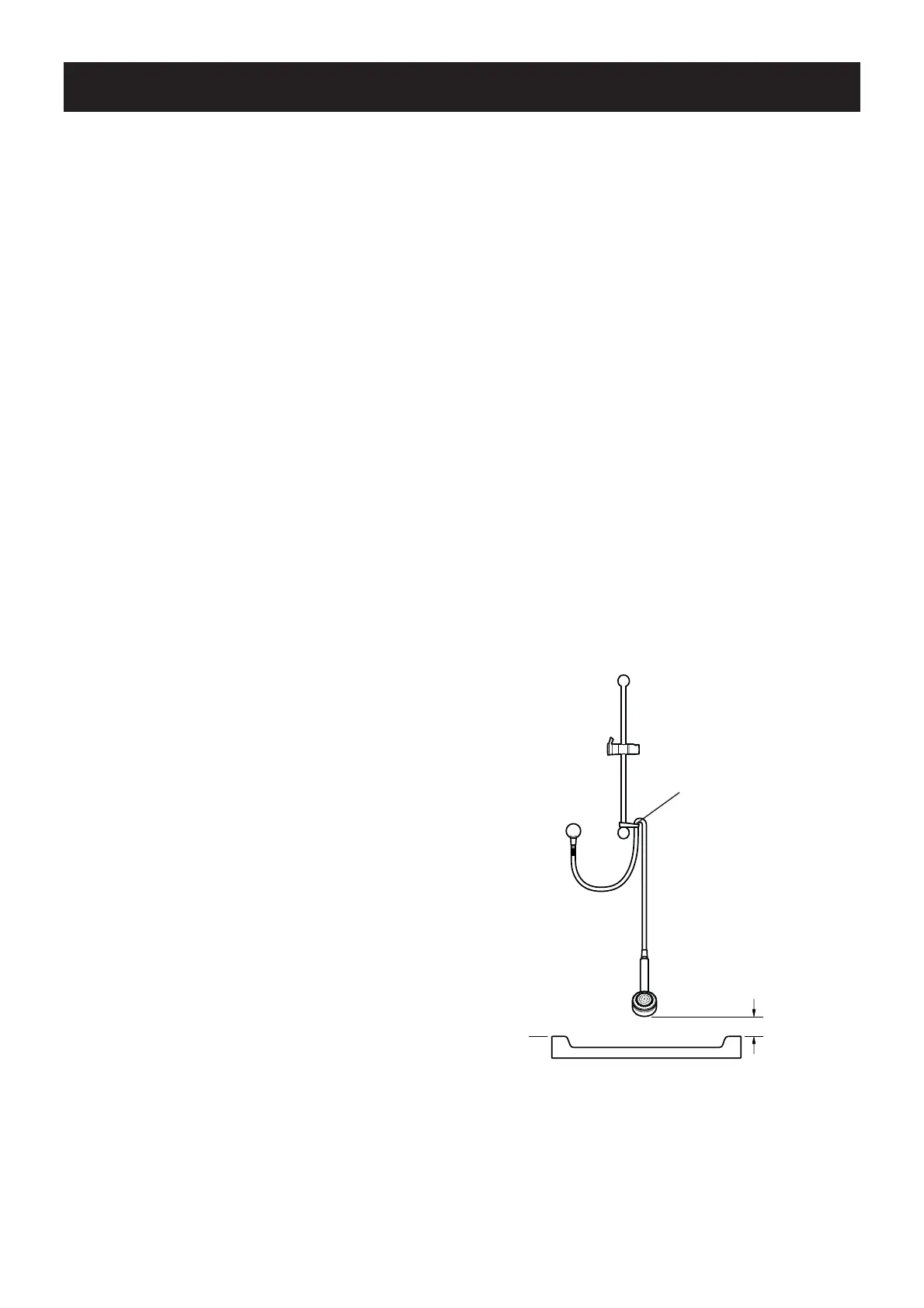
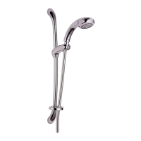
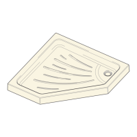
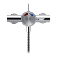
9. Decide on a suitable position for the
Mixer. The position of the Mixer and the
Shower Fittings must provide a minimum
gap of 25 mm between the spill-over level
of the shower tray/bath and the handset.
This is to prevent back-siphonage. For
further information on the installation
of the Shower Fittings, refer to the
“Shower Fittings Installation and User
Guide.”
Note! Only use Shower Fittings
recommended by the manufacturer or supplier.
INSTALLATION
25 mm
Spill Over
Level
Hose Retaining
Ring


 To Next Page