25
Cable and Jumper Connections for Main Board, Core Board and Adder Modules
6.3 OCAC-302 Output Class-A Converter Adder Module
Figure 8 OCAC-302 Output Class-A Converter Adder Module
Indicating circuits must be wired from the OCAC-302 to the main Fire Alarm board. For
example indicating circuit 1 positive (red wire) and negative (black wire) is wired from the
Class A converter module to the positive and negative terminals of Indicating circuit 1 on the
Main Fire Alarm board.
The actual indicating zone is wired from the SIGNAL OUT positive and negative to the
signaling devices and then wired back to the SIGNAL RET positive and negative.
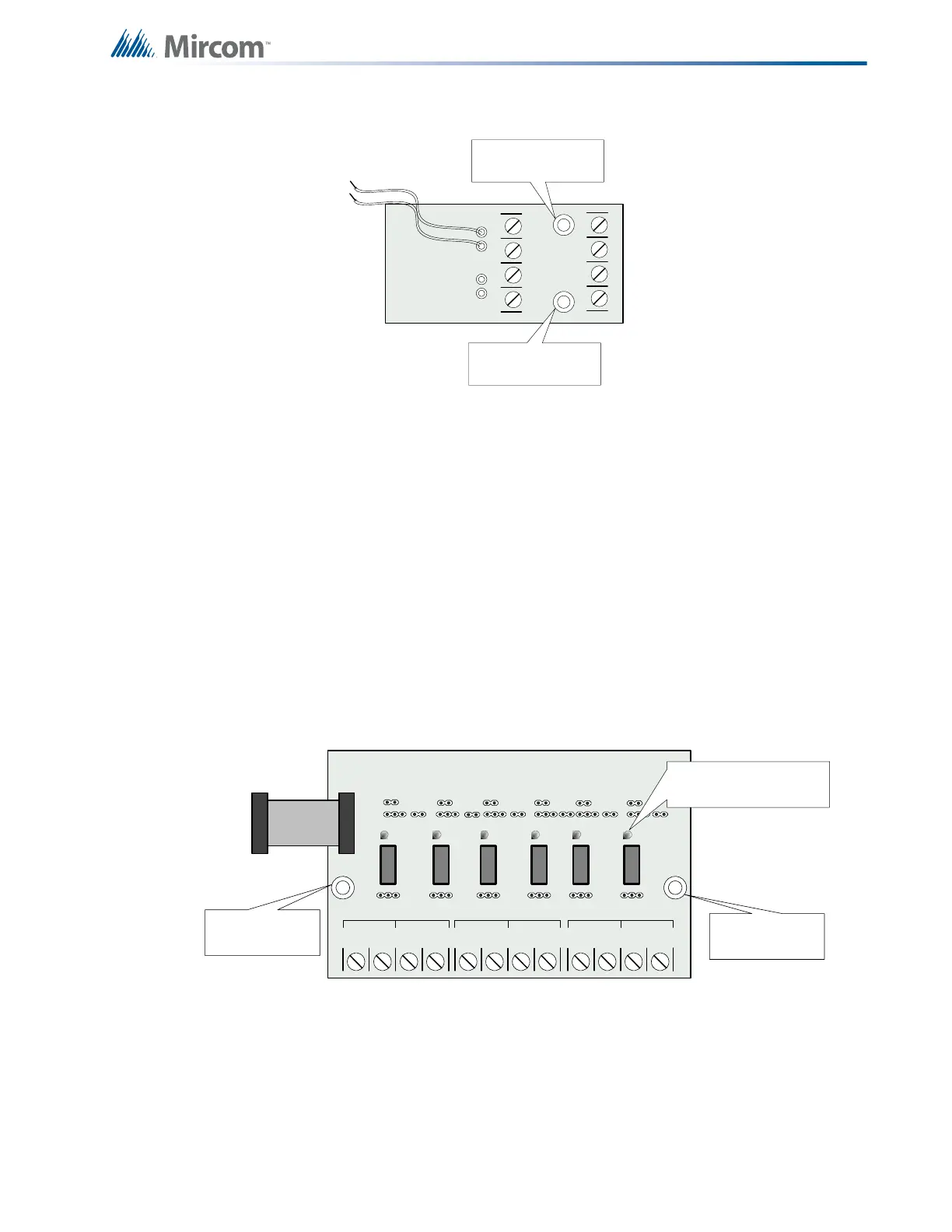
6.4 RM-306 Relay Adder Module
Cable from P1 of the RM-306 is connected to P4 on the Main Fire Alarm Board. The jumpers
located above each relay on the RM-306 are used to configure the relays. The jumpers
located below the relays are used to select either normally open contacts or normally closed
contacts.
Figure 9 RM-306 six relay adder module
- SIG1 OUT +- SIG2 OUT+
- SIG1 RET+- SIG2 RET+
BLK RED
BLK RED
mounting hole for
#6-32 screws
OCAC-302
mounting hole for
#6-32 screws
NO/NC C
RELAY 1
NO/NC C
RELAY 2
NO/NC C
RELAY 3
NO/NC C
RELAY 4
C
RELAY 5
NO/NC C
RELAY 6
NO/NC
mounting hole
for #6-32 screws
mounting hole
for #6-32 screws
INDIVIDUAL GREEN
RELAY STATUS LEDs
Connect to P6 on the
main fire alarm board
 Loading...


