25
Cable and Jumper Connections for Main Board and Adder Modules
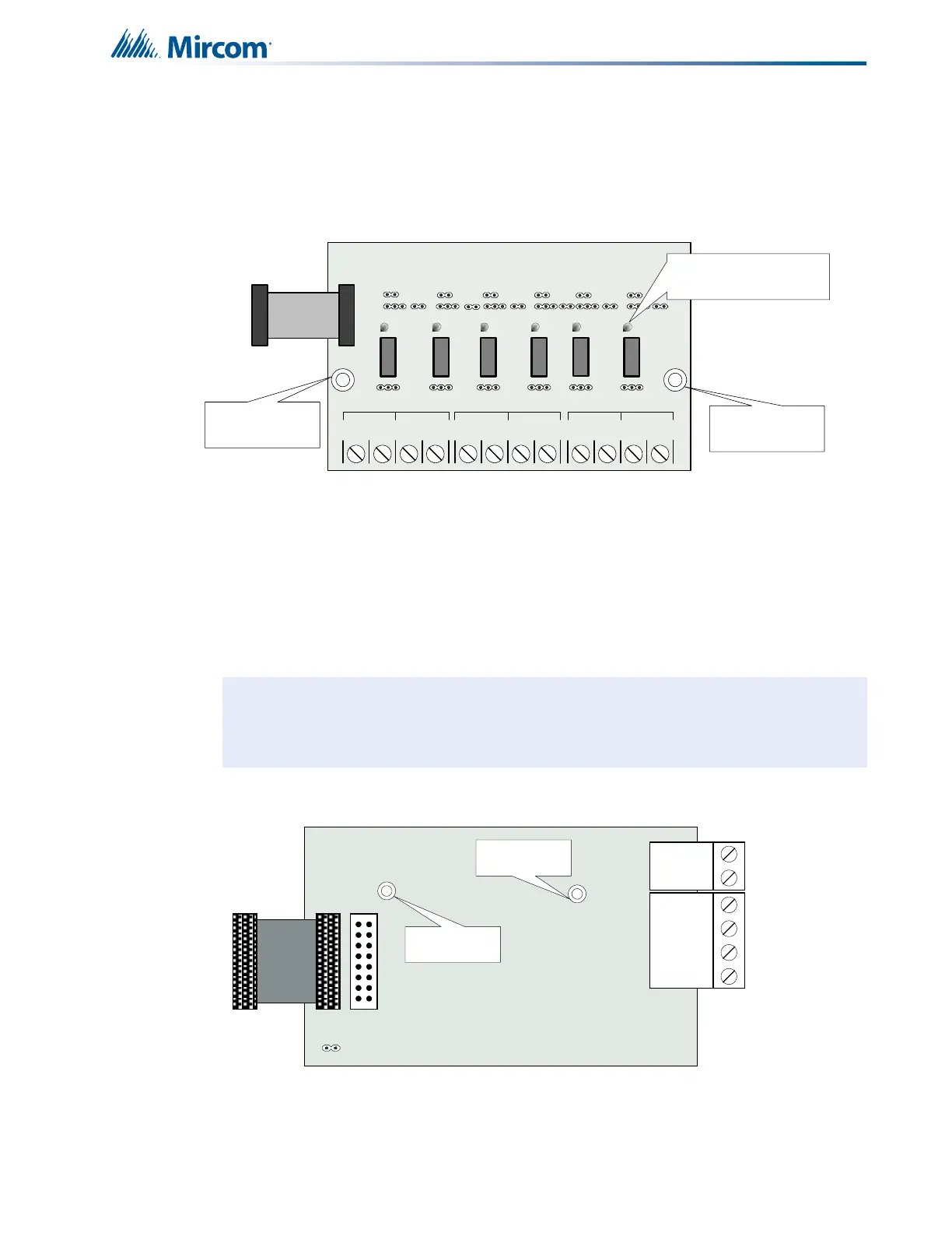
6.4.3 RM-306 Six Relay Adder Module
Cable from P1 of the RM-306 is connected to P6 on the Main Fire Alarm Board. The jumpers
located above each relay on the RM-306 are used to configure the relays. The jumpers
located below the relays are used to select either normally open contacts or normally closed
contacts.
Figure 12 RM-306 six relay adder module
6.4.4 Programming the relays
See explanation in Figure 11.
6.5 Polarity Reversal and City Tie Module (Model PR-300)
Figure 13 Polarity reversal and city tie module
The following hardware configuration must be performed before installing the PR-300.
P1 Cable from RM-306 Relay Adder Module connects to P6 on Main Fire Alarm
Board.
Note: Relay programming should be done before installing the board.
NO/NC C
RELAY 1
NO/NC C
RELAY 2
NO/NC C
RELAY 3
NO/NC C
RELAY 4
C
RELAY 5
NO/NC C
RELAY 6
NO/NC
mounting hole
for #6-32 screws
mounting hole
for #6-32 screws
INDIVIDUAL GREEN
RELAY STATUS LEDs
Connect to P6 on the
main fire alarm board
POLARITY
REVERSAL
ALARM
POLARITY
REVERSAL
SUPV
CITY
TIE
+ | - + | - + | -
JW4
P1 P2
Mounting hole for
#6-32 screws
Mounting hole for
#6-32 screws