35
Field wiring
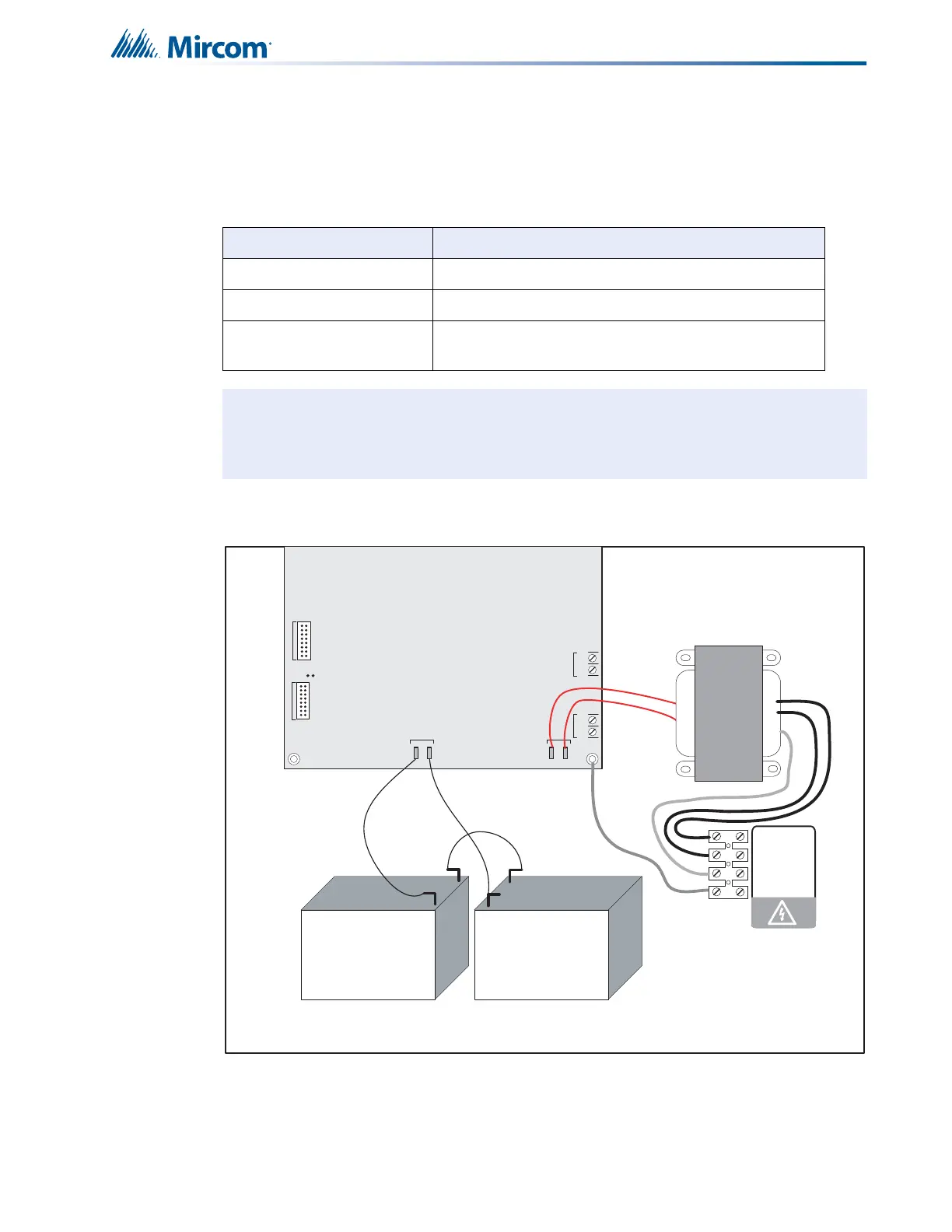
7.6 Power supply connection
The power supply is part of the Main Chassis. The ratings are:
Wire the power supply as shown in Figure 25 using the proper wire gauge. See Appendix C:
Specifications for power supply specifications.
Figure 25 Power supply connection
Table 2 Power Supply Ratings
Type Rating
Electrical Input rating 120VAC, 60Hz, 3A\ 240 VAC, 50 Hz, 1.5A
Power supply total current 6A maximum
Battery fuse on Main
module
10A, slow blow micro fuse
Caution: Do not exceed power supply ratings.
JW1
-+-+
SIG 3SIG 4
TO PR- 30 0 MO DULE
TO RM-312/RM-306 RELAY
MOD U LE
P1 P2
P3 P4
+
_
BATTERY
SEC. TX
blk
red
red
red
red
blk
+
+
_
_
Battery Battery
NOTE: TO PREVENT SPARKING, CONNECT BATTERIES AFTER THE
SYSTEM MAIN A.C. POWER IS TURNED ON
red
green
blk
yellow
240 VAC 50Hz
120 VAC 60Hz
N
GND