4 Installation
4.1 DIN rail Mounting
22
FX3U-1PG User's Manual
4.1 DIN rail Mounting
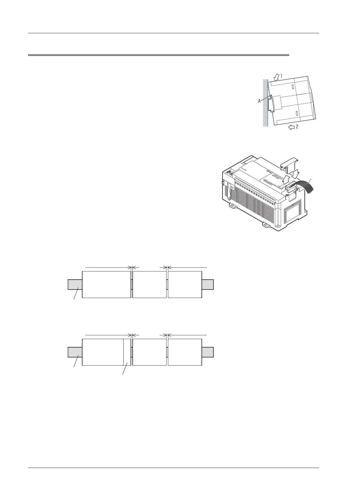
The product may be mounted on a 35 mm wide DIN46277 (DIN rail).
1 Fit the upper edge (A in the figure to the right) of the DIN
rail mounting groove onto the DIN rail.
2 Push the product onto the DIN rail.
• An interval space of 1 to 2 mm (0.04" to 0.08") between each unit is necessary.
3 Connect the extension cable.
Connect the extension cable (B in the figure to the right) to
the main unit, I/O extension unit/block or special function
unit/block on the left side of the product.
For information on the extension cable connection
procedure, refer to the respective product PLC manual.
→ Refer to FX3U Hardware Edition.
→ Refer to FX
3UC Hardware Edition.
• Example of installation on DIN rail
- In the case of the FX
3U PLC
- In the case of the FX
3UC PLC
B
FX3U Series
main unit
DIN rail
FX3U-1PG
1 to 2 mm
(0.04" to 0.08")
Other
extension
equipment
1 to 2 mm
(0.04" to 0.08")
FX3UC Series
main unit
DIN rail
FX3U-1PG
1 to 2 mm
(0.04" to 0.08")
Other
extension
equipment
1 to 2 mm
(0.04" to 0.08")
FX2NC-CNV-IF or
FX
3UC-1PS-5V

 Loading...


