APPENDIX
App. - 9
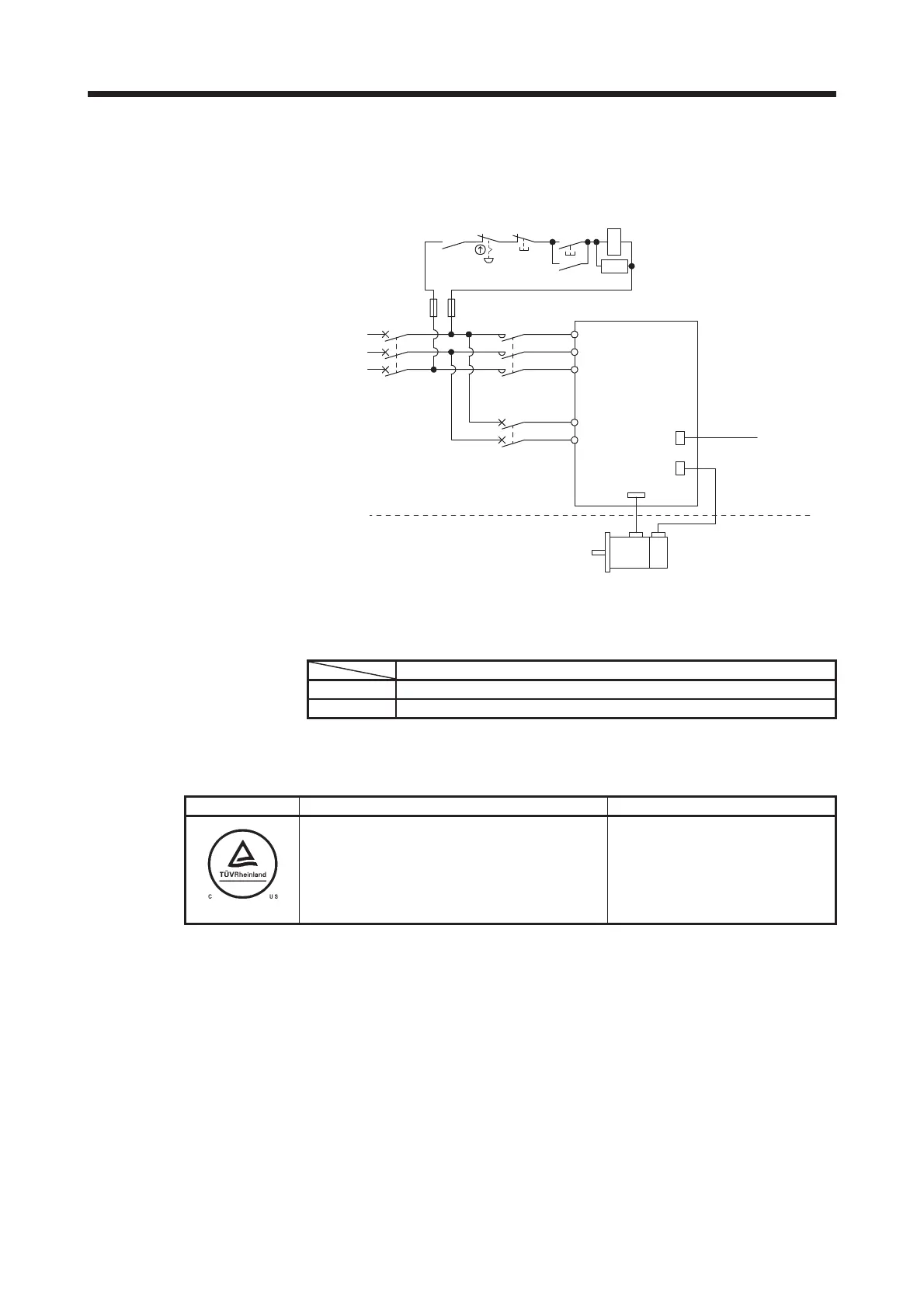
(9) Configuration diagram
Representative configuration diagram example to conform to the UL/CSA standard is shown below. The
grounding wiring is excluded from the figure configuration.
CN1
CN2
UVW
ࠦࡦ࠻ࡠ
ࠛࡦࠦ࠳ࠤࡉ࡞
ᓮ⋚
ᯏ
ࠨࡏࡕ࠲
ࠛࡦࠦ࠳
ࠨࡏࠕࡦࡊ
㔚Ḯ
⋧AC200V
㨪240V
㓚
RA1
ࠝࡈ
MC
ࠝࡦ
M
C
SK
㕖Ᏹᱛ
ࠬࠗ࠶࠴
L11
L21
L1
L2
L3
MC
MCCB
߹ߚߪ
ࡅࡘ࠭
MCCB
߹ߚߪ
ࡅࡘ࠭
(10) Power supply
The control circuit provides safe separation to the main circuit in the servo amplifier.
Connector/terminal
Main circuit CNP1/CNP2/CNP3/TE1/TE2/TE3/TE4
Control circuit CN1/CN2/CN3/CN4/CN5/CN8
(11) UL/CSA standard certification mark on products
The following mark shows UL/CSA standard certification of MR-J4 multi-axis servo amplifiers.
Mark Certification Body Remarks
TUV Rheinland of North America Inc.
Independent public testing institution in North America
National recognized testing laboratory (NRTL)
NRTL listing mark (UL 508C)
App. 6 Compliance with KC mark
For the situation of compliance, contact your local sales office.
When you use the products in South Korea, note the following.
決
匶匶垚
櫋怺殯
(A
匏
)
洊沖砒洇穯匶匶嵢昢
砖
廪沖
嬖垚
斲殯沖垚
決
洖汊
渂汞穞柢匶
愚岂彶
,
儆洛歾汞
滆櫳櫖昢
斲殯穞垚
冉汊
徯洇求
嵢
穯城埪
.
(The product is for business use (Class A) and meets the electromagnetic compatibility requirements. The
seller and the user must note the above point, and use the product in a place except for home.)
MCCB
or
fuse
Malfunction
RA1
OFF
ON
EMG stop
switch
MCCB
or
fuse
Servo motor
Servo amplifier
Encoder
Encoder cable
Controller
Cabinet side
Machine side
3-phase
200 V AC to
240 V AC

 Loading...


