2 - 5
2 SYSTEM CONFIGURATION
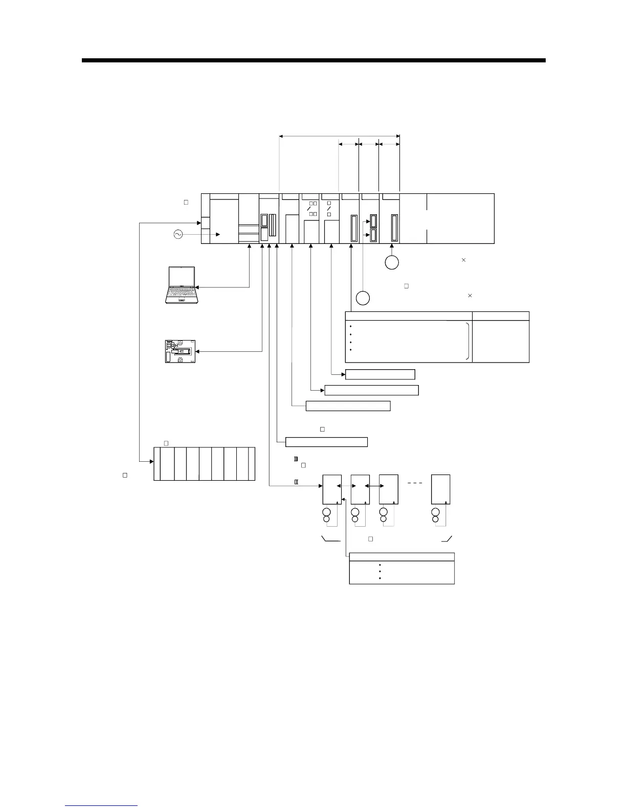
2.1.2 Q172DCPU System overall configuration
d2
d1
MR-J3- B model Servo amplifier,
Up to 8 axes
d3
E
M
E
M
E
M
E
M
SSCNET cable
(MR-J3BUS M(-A/-B))
SSCNET (CN1)
d8
External input signals of servo amplifier
Upper stroke limit
Proximity dog
Lower stroke limit
PLC CPU/
Motion CPU
100/200VAC
Q172D
CPU
(Q3 DB)
QnUD(H)
CPU
Personal Computer
IBM PC/AT
Motion CPU control module
USB/RS-232
Q61P
Main base unit
I/O module /
Intelligent function module
Extension cable
(QC B)
P
o
w
e
r
s
u
p
p
l
y
m
o
d
u
l
e
(Q6 B)
UP to 7 extensions
Extension base unit
QI60
QX
Interrupt signals (16 points)
Analogue input/output
QY
Q6 AD
Q6 DA
Input/output (Up to 256 points)
M
a
n
u
a
l
p
u
l
s
e
g
e
n
e
r
a
t
o
r
i
n
t
e
r
f
a
c
e
m
o
d
u
l
e
S
y
n
c
h
r
o
n
o
u
s
e
n
c
o
d
e
r
i
n
t
e
r
f
a
c
e
m
o
d
u
l
e
S
e
r
v
o
e
x
t
e
r
n
a
l
s
i
g
n
a
l
s
i
n
t
e
r
f
a
c
e
m
o
d
u
l
e
(Up to 1 module)
Q172D
EX
(MR-HDP01)
P
Manual pulse generator 3/module
(Up to 6 modules)
(Q170ENC)
E
Serial absolute synchronous encoder 2/module
Serial absolute synchronous encoder cable
(Q170ENCCBL M)
Q172D
LX
Q173D
PX
External input signals
FLS
8 axes/module
Number of Inputs
(Up to 4 modules)
RLS
STOP
DOG/CHANGE : Proximity dog/
Speed-position switching
: Stop signal
: Lower stroke limit
: Upper stroke limit
Battery holder unit
Q170DBATC
EMI forced stop input (24VDC)
Forced stop input cable
(Q170DEMICBL M)

 Loading...


