127
CHAPTER 6 CPU MODULE
6
6.1 Part Names
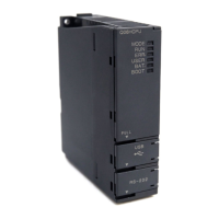
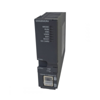
6.1.2 High Performance model QCPU, Process CPU and Redundant CPU
No. Name Application
1) Module fixing hook Hook used to secure the module to the base unit. (Single-motion installation)
2) MODE LED
Indicates the mode of the CPU module.
On (green): Q mode
Flash (green): Forced on and off for external I/O registered
3) RUN LED
Indicates the operating status of the CPU module.
On: The RUN/STOP switch is set to "RUN".
Off: The RUN/STOP switch is set to "STOP".
(The standby system Redundant CPU module in the backup mode does not turn on even
when the RUN/STOP switch is set to "RUN" but the module is stopped.)
When an error is detected and operation must be halted due to the error
Flash:
Parameters or programs are written with the RUN/STOP switch set to "STOP" and then
the RUN/STOP switch is turned from "STOP" to "RUN."
When the operation mode is changed from the backup mode to the separate mode in the
Redundant CPU system, the RUN LED of the standby system side CPU module flashes.
To turn on the RUN LED after writing the program, perform the following operations.
• Set the RUN/STOP switch from "RUN" "STOP" "RUN".
• Reset with the RESET/L. CLR switch.
• Restart the programmable controller power.
To turn on the RUN LED after writing the parameters, perform the following operations.
• Reset with the RESET/L. CLR switch.
• Restart the programmable controller power.
(If the RUN/STOP switch is set from "RUN" "STOP" "RUN" after changing the
parameters, network parameters and intelligent function module parameters will not be
updated.)
4) ERR. LED
On: Detect on of self-diagnosis error which will not stop operation, except battery error.
(When operation continued at error detection is set in the parameter setting.)
Off: Normal
Flash:
Detection of the error that stops operation.
When automatic write to the standard ROM is completed normally. (The BOOT LED
flashes together.)
5) USER LED
On: Error detected by CHK instruction or annunciator (F) turned ON
Off: Normal
Flash: Execution of latch clear
6) BAT. LED
On: Battery error due to reduction in battery voltages of CPU module or memory card.
Off: Normal
7) BOOT LED
On: Start of boot operation
Off: Non-execution of boot operation
Flash:
When automatic write to the standard ROM is completed normally. (The ERR. LED
flashes together.)
8) Serial number display Shows the serial number printed on the rating plate.
9) Memory card EJECT button Used to eject the memory card from the CPU module.
10) Memory card installing connector Connector used for installing the memory card to the CPU module.
11)
USB connector
*1
Connector for connection with USB-compatible peripheral device. (Connector type B)
Can be connected by USB-dedicated cable.
(Not available for Q02CPU.)
12)
RS-232 connector
*1
Connector for connecting a peripheral device by RS-232.
Can be connected by RS-232 connection cable (QC30R2).

 Loading...


