Appendix - 60
Appendices
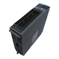
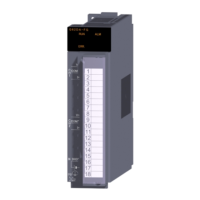
Appendix 4.2 Differences with LD77MH models
(1) Differences of performance specifications
Model
Item
QD77MS2 QD77MS4 QD77MS16 LD77MH4 LD77MH16
Number of control axes 2 4 16 4 16
Operation cycle [ms] 0.88/1.77 0.88 0.88/1.77
Starting time
(1-axis linear)
Trapezoidal
acceleration/
deceleration
0.88ms 1.77ms 0.88ms 1.77ms
S-curve
acceleration/
deceleration
SSCNET communication
SSCNET
/H or SSCNET
SSCNET
Compatible servo amplifier
MR-J4-_B_/MR-J4W_-_B/MR-J4-_B_-RJ/
MR-J3-_B_/MR-J3W-_B/MR-J3-_B_-RJ006/
MR-J3-_BS_/MR-J3-_B_-RJ004/
MR-J3-_B-RJ080W/MR-JE-_B
MR-J3-_B_/MR-J3W-_B/MR-J3-_B_-RJ006/
MR-J3-_BS_/MR-J3-_B_-RJ004/
MR-J3-_B-RJ080W
(Note-1)
Controlled
servo
parameter
group
SSCNET
/H
PA, PB, PC, PD, PE, PS, PF, Po, PL —
SSCNET
PA, PB, PC, PD, PE, PS, PF, Po PA, PB, PC, PD, PE, PS, PF
(Note-1)
, Po
(Note-1)
Machine OPR function
(OPR method)
6 types
(Near-point dog method, Count method 1) 2), Data
set method, Scale origin signal detection method,
Driver OPR method)
5 types
(Near-point dog method, Count method 1) 2),
Data set method, Scale origin signal detection
method)
External signal selection function
External input signal of QD77MS
(FLS, RLS, DOG, STOP, DI) /
External input signal of servo amplifier
(FLS, RLS, DOG) / external input signal via CPU
(buffer memory : FLS, RLS, DOG)
External input signal of servo amplifier
(FLS, RLS, DOG) / external input signal via
CPU (buffer memory : FLS, RLS, DOG)
Connection connector
A6CON1, A6CON4: Soldering type, Optional
A6CON2: Crimp contact type, Optional
A6CON3: Pressure-displacement type, Optional
LD77MHIOCON: Soldering type
Applicable wire size
A6CON1, A6CON4: 0.3mm
2
A6CON2: AWG 28 to AWG24 (0.08 to 0.2 mm
2
)
A6CON3: AWG28 (Stranded, 0.08mm
2
)
AWG30 (Solid, 0.05mm
2
)
LD77MHIOCON: AWG30 to AWG24
(0.05 to 0.2 mm
2
)
5VDC internal current
consumption [A]
0.6 0.75 0.55 0.70
Number of module occupied
slots
1 2
Outline dimensions [mm(inch)] 98.0(3.86) (H)×27.4(1.08) (W)×90.0(3.54) (D) 90.0(3.54) (H)×45.0(1.77) (W)×95.0(3.74) (D)
Mass [kg] 0.15 0.16 0.22
Saving area for servo parameter
Internal memory (nonvolatile)
Flash ROM
Programming tool GX Works2, MR Configurator2
GX Works2, MR Configurator2/
GX Developer, GX Configurator-QP
(Note-1)
,
Upper limit value of electronic
gear setting range
(Note-2)
20000
(Note-1): GX Configurator-QP does not support with a part of LD77MH4 function and LD77MH16.
(Note-2): The value varies depending on the product information as follows.
Before 150320000000000 : 20000,
150320000000000 or later: 320000

 Loading...


