MITSUBISHI ELECTRIC 7011A SERIES UPS
MITSUBISHI
ELECTRIC
7011A SERIES UPS
OWNERS / TECHNICAL MANUAL
Page Number:
1-8
The rotary maintenance bypass switch is shown as 52CS in Figure 1.4. 52CS is a two position
four point make-before-break transfer switch.
The two positions are identified as NORMAL and BYPASS. In the NORMAL position the load is fed
by the UPS - either through the inverter or through the static bypass line. In the BYPASS position
the load is powered by an external source such as the utility or a generator. This transfer operation
must be made while the UPS is in the static bypass mode.
For transfer procedure to place the UPS in maintenance bypass mode, or from bypass mode to
normal operation mode, refer to section 3.6 Maintenance Bypass Set-up Procedures.
(For Service Personnel Only)
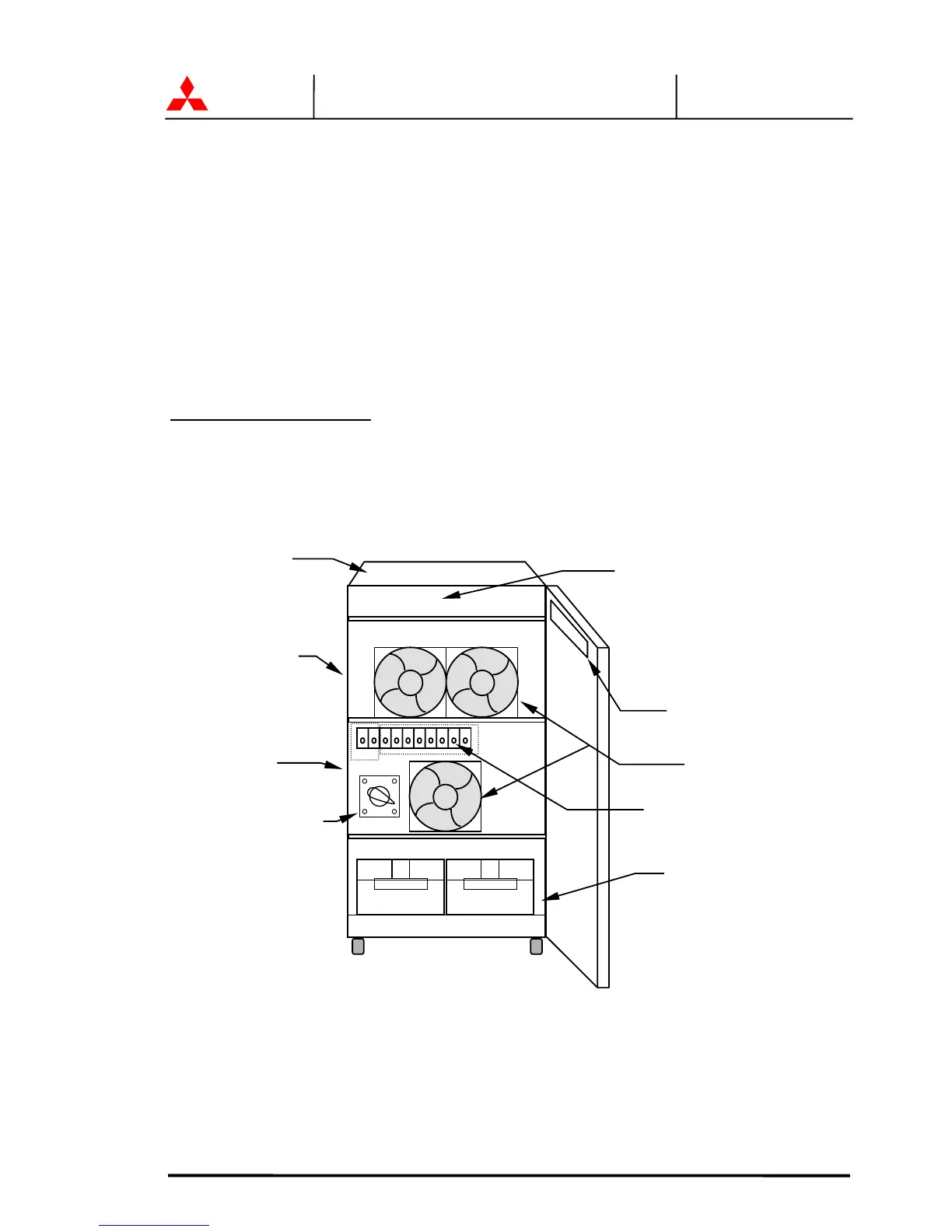
FIGURE 1.5 UPS Parts Location(6kVA)
.
1.Relay I/F PCB
RYER-A
UPS module
FRONT VIEW
Converter &
Inverte
 Loading...