MITSUBISHI
ELECTRIC
7011A SERIES UPS
OWNERS / TECHNICAL MANUAL
Page Number:
3-12
MITSUBISHI ELECTRIC 7011A SERIES UPS
3.4.2 PROCEDUR FOR INTERNAL BATTERY CONNECTION
Procedures for battery connection are as follows.
Please note, these procedures must be performed after the external cables are connected. For
procedures for external cable connection, please refer to “3.3 PROCEDURE FOR CABLE
CONNECTIONS”.
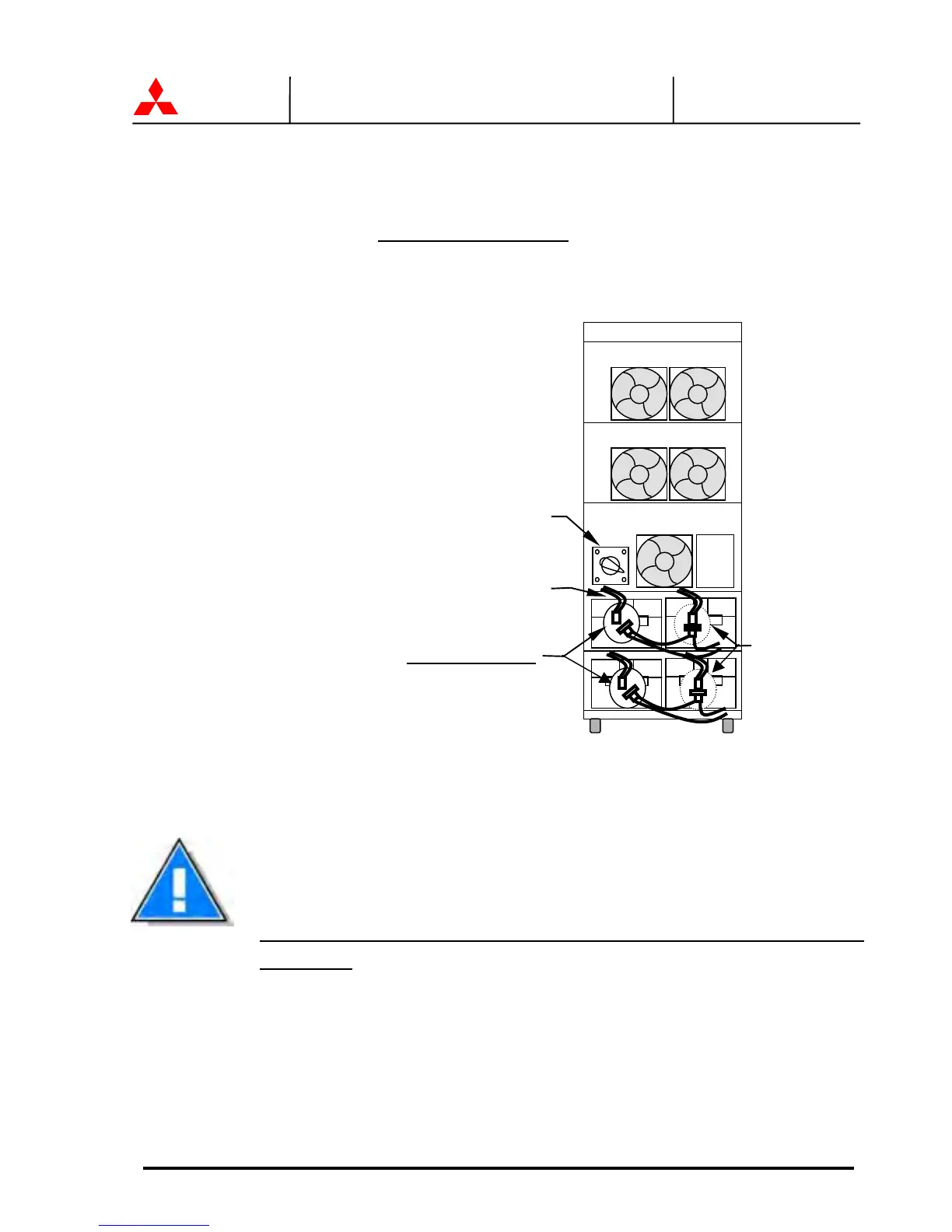
1. Remove the straps, which hold the batteries.
2. As shown in the left figure, when shipped, there
are unconnected connectors for safety. Connect
these unconnected connectors.
FIGURE 3.8 Battery Connection when shipped
For your safety, one side of the connectors is not connected when shipped.
Connection of the battery module connectors may apply voltage to B+ / B-
connectors on the Field Wire Terminal Block on the rear side of the UPS.
Please be sure to connect the external cables before connecting the battery
connectors.
Fan Fan
Fan
DC
Fuse
Fan Fan
Battery Module
Connected
Not connected
Maintenance bypass
transfer switch 52CS
 Loading...