controller. For applicable fuses to be used for replacement, refer to the table below.
Note) Although the figure is the CR750 controller, the fuse to
replace also by the CR751 controller is in the same
position.
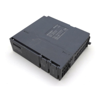
Remove the six top cover fixing screws (M3 x 6), and remove the top cover.
Top cover
Top cover fixing screws
・ CR751 controller: Two screws each at right and left and the rear.
・ CR750 controller: Two screws each at right and left and the front.
Top view inside the controller
CR750: controller front side
Pneumatic hand's power fuse (F3 or F5)
Model: LM16
Note) Display "large1.6A" on surface of the fuse.
(is not "LM16")
CR751: controller front side
Hand fuse
(1 pc.)
Brake fuse
(2 pcs.)
*1
Table of applicable fuses
Note) The fuse part numbers vary according to the sub-number n of the converter circuit board (YZ801n) mounted inside the controller. The
sub-number of the converter circuit board is marked on the area indicated by “*1” in the figure shown above.
Ex.) Sub-number is “A” (YZ801A) ................Hand fuse: F3, Brake fuse: F1 and F2
Sub-number is “B” (YZ801B) ................Hand fuse: F5, Brake fuse: F3 and F4
Robot series Controller’s serial number
Converter
circuit board
Hand fuse Brake fuse
Part
number
Model
Part
number
Model
RH-3/6/12/20FH series,
RV-2/4/7F series
F1xxxxxx/F2xxxxxx/R1xxxxxx/R2xxxxxx YZ801A F3 LM16 F1、 F2 LM16
F1Axxxxxx/F2Axxxxxx/R1Axxxxxx/R2Axxxxxx YZ801B F5 LM16 F3、 F4 LM16
RV-13/20F series,
RV-7FLL series
F1xxxxxx/F2xxxxxx/R1xxxxxx/R2xxxxxx YZ801A F3 LM16 F1、 F2 LM32
F1Axxxxxx/F2Axxxxxx/R1Axxxxxx/R2Axxxxxx YZ801B F5 LM16 F3、 F4 LM32
 Loading...