Appendix-65
2.4 Errors involving change in specification
The specification of the following errors changes when the safety monitoring function used in the robot safety
option (4F-SF001-01) is enabled.
(1) To reset the following errors while the safety monitoring function is enabled, reset the power supply.
(2) When the emergency stop button on the operation panel is pressed while the safety monitoring function is
enabled, as well as H0060 (EMG signal is input. (O.Panel)), H0050 (EMG signal is input. (external)) occurs.
15
Brake is not working properly
Cause
[Occurs only when operating manually]
・ T/B operation error.
・ The enabling device input is open.
[Occurs when operating manually and automatically]
・ Faulty connection of the cables that run between devices.
・ Brake failure.
Measures
[Occurs only when operating manually]
・ Check the T/B operation (operation buttons, 3 position enabling switch, etc.).
・ Short circuit the CNUSR connector’s enabling device input.
[Occurs when operating manually and automatically]
・ Check the mating of the cables that run between devices.
If no improvement is made after carrying out the above measures, please contact the manufacturer.
16
The communication fault occurs by the equipment connected to the Ethernet cable inside the robot arm.
Cause
・ The Ethernet cable is not connected surely.
・ There are the device etc. which cause the noise and the noise has applied to the Ethernet cable.
Measures
・ Confirm that the Ethernet cable is connected surely.
・ If the effect by the noise can be considered, find out the noise source and remove the noise. Moreover, adds the
grounding and ferrite core of the Ethernet cable if needed.
Recommendation ferrite core: E04SR301334 (SEIWA ELECTRIC MFG. Co.,Ltd.)
17
The T/B does not display anything.
Cause
・The fuse (4A fuse) installed at the bottom of the 24 V power supply circuit in the controller may have blown out.
For the fuse blowout, the emergency stop made by the customer may be the cause, or there may be a ground
fault or short circuit with the 24 V power supply in the wiring of a door switch, enabling device, etc.
・ The T/B might be out of order.
Measures
・ Investigate and correct the ground fault or short circuit portion in the wiring made by the customer. Then,
replace the fuse inside the controller. Refer to Page 60, "Fig.2-3 : Fuse (F8) exchange place (CR750/CR751
controller)" for details. (On details of the fuse, contact the manufacturer.)
If no improvement is made after carrying out the above measures, please contact the manufacturer.
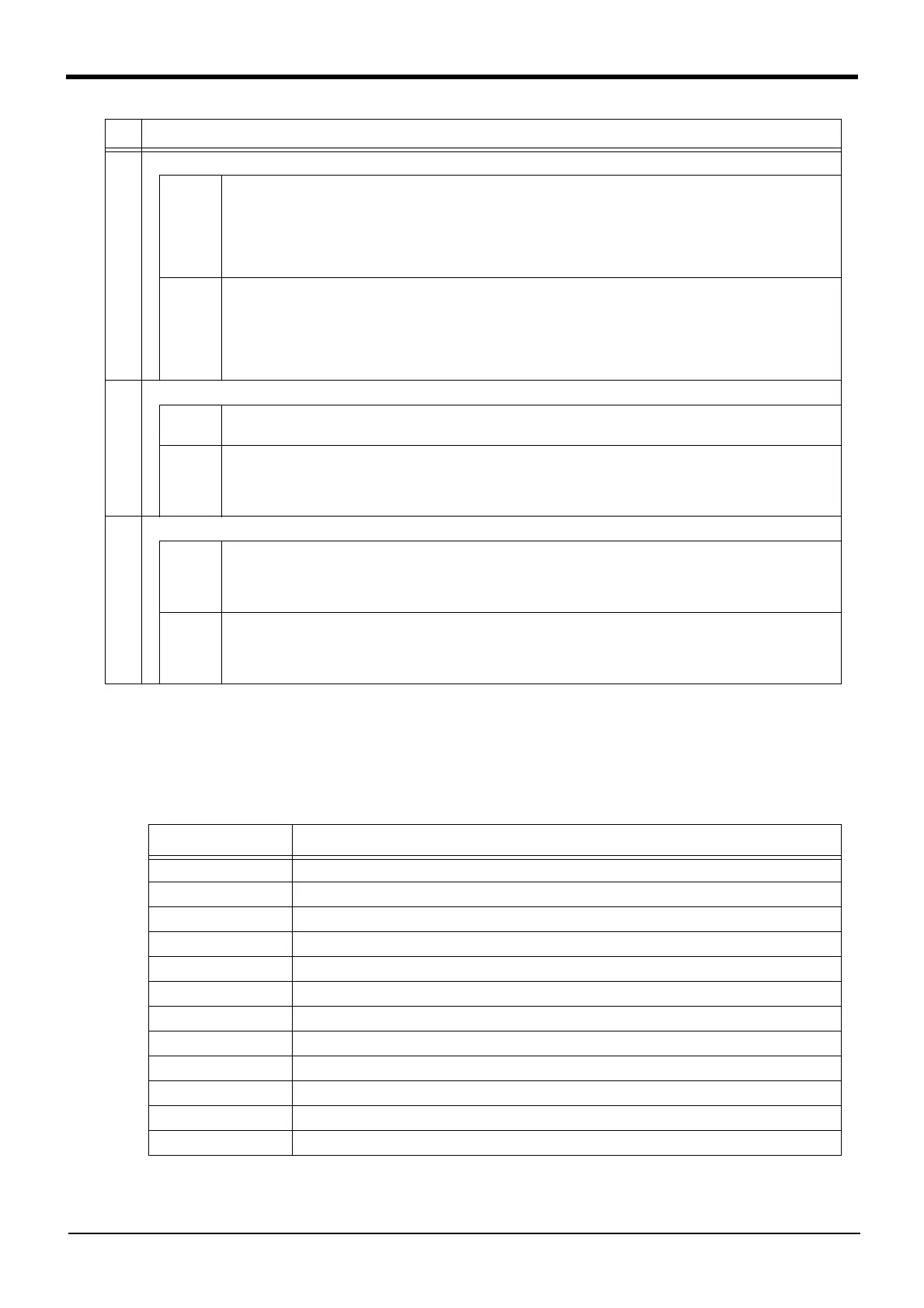
Error Error message
H0039 Door Switch Signal line is faulty..
H0044 OP Mode key line is faulty.
H0045 Faulty Line (T/B Enable Switch).
H0046 Faulty wiring (Enabling Device).
H0051 Wiring of the external emergency stop is abnormal.
H0061 EMG line is faulty.(O.Panel)
H0071 EMG line is faulty.(T.Box)
H0074 Faulty line (T/B Enable/Disable).
H1680 Cannot servo ON (timeout)
H1681 Unexpected servo OFF
H1682 Servo ON Timeout (Safety relay).
H1683 Servo ON Timeout. (Contactor)
No. Issue
 Loading...