131
APPENDIX
Appendix 1-1 Replacement of the FR-S500 series
(1) Instructions for installation
1) Removal procedure of the front cover and wiring cover was changed. (Refer to page 4)
2) FR-SW0-SETUP, FR-SW1-SETUP, FR-SW2-SETUP (setup softwares) can not be used.
(2) Instructions for continuous use of the FR-PU04 (parameter unit)
1) For the FR-D700 series, many functions (parameters) have been added. When setting these parameters, the
parameter name and setting range are not displayed. User initial value list and user clear of the HELP function can
not be used.
2) For the FR-D700 series, many protective functions have been added. These functions activate, but all faults are
displayed as "Fault 14". When the faults history has been checked, "E.14" appears. Added faults display will not
appear on the parameter unit.
3) User initial value setting can not be used.
4) User registration/clear can not be used.
5) Parameter copy/verification function can not be used.
(3) Parameter resetting
It is easy if you use FR Configurator SW3 (setup software).
(4) Main differences and compatibilities with the FR-S500 series
Appendix1 For customers replacing the conventional model
with this inverter
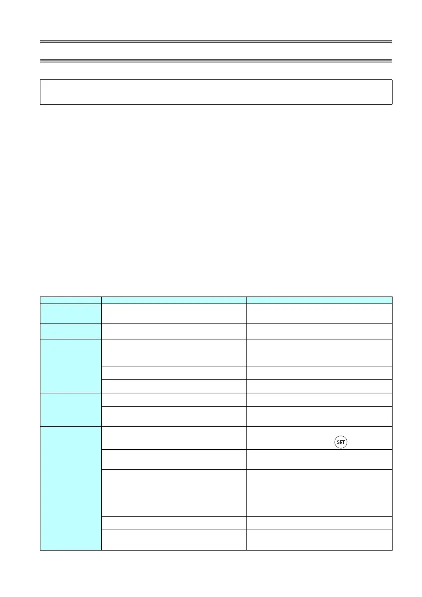
Item FR-S500 FR-D700
Control method
V/F control
Automatic torque boost
V/F control
General-purpose magnetic flux vector control
Optimum excitation control
Output frequency
range
0.5 to 120Hz 0.2 to 400Hz
Changed initial value
Pr. 0 Torque boost
FR-S520E-1.5K to 3.7K: 6%
FR-S540E-1.5K, 2.2K: 5%
FR-S520SE-1.5K: 6%
FR-D720-1.5K to 3.7K: 4%
FR-D740-1.5K, 2.2K: 4%
FR-D720S-1.5K: 4%
Pr.1 Maximum frequency
60Hz 120Hz
Pr. 12 DC injection brake operation voltage
0.4K to 3.7K: 6% 0.4K to 3.7K: 4%
Changed setting
increments
Pr. 37 Speed display
0.1 0.001
H2(Pr. 504) Maintenance timer alarm output set time
Time per increments: 1000h
Initial value: 36 (36000h)
Pr.504 Maintenance timer alarm output set time
Time per increments: 100h
Initial value: 9999 (not function)
Changed setting value
Pr. 52 Control panel display data selection
1: Output current
Pr.52 DU/PU main display data selection
0/100: Output current (select with )
Pr.54 FM terminal function selection
0: Output frequency (initial value),
1: Output current
1: Output frequency (initial value),
2: Output current
Pr. 60 to Pr. 63 Input terminal function selection
5: STOP signal (start self-holding selection)
6: MRS signal (output stop)
9: JOG signal (Jog operation selection)
10: RES signal (reset)
---: STR signal (reverse rotation command)
Pr. 178 to Pr. 182 Input terminal function selection
5: JOG signal (Jog operation selection)
6: None
24: MRS signal (output stop)
25: STOP signal (start self-holding selection)
61: STR signal (reverse rotation command)
62: RES signal (reset)
Second applied motor
Pr. 71 = 100, 101 Pr. 450 Second applied motor
Pr. 73 Terminal 2 0 to 5V, 0 to 10V selection
0: 0 to 5V (initial value),
1: 0 to 10V
Pr. 73 Analog input selection
0: 0 to 10V,
1: 0 to 5V (initial value)
 Loading...


