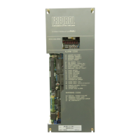
3.3 FR-SFJ status display and parameter settings
c
c
Operation status is displayed by the 7-segment LED readout
on card SFJ-CA1 and parameters can be set by DIP switches.
Status display and parameter settings depend on ROM version
of card SFJ-CA1 card.
For ROM version A@ . . . . .
(A) 3. 3. 1
For ROM version BO and thereafter . . . .
(B)
3. 3. 1
When FR-SFJ is connected to M300 CNC through bus line, sta-
tus can be displayed and parameter can be set on the NC CRT.
(For details,
refer to 3.5.)
DIP switch settings and functions
Since DIP switch settings must be changed only when test op-
eration is required, they should not be changed during normal
operation.
Mode
DIP switch setting
Function
/
(0:
Set position)
1
I
1
j
i
Normal
operation
;
g@$
!
I
,
I
I_i_
_--_._
-.._-
_-._._...
.__!_-_-_-_-
._-_.._
-_
__.__-__
___.
___
_.
__
_
2
i
1
2 3
[
Spindle parameters displayed by NC
/
CRT are ignored.
,
ON
!o/
I
I
;
I
,-
j
‘A
j
c
]
When FR-SFJ is connected to M300 CNC,
the spindle parameters set and
dis-
I
I
played on the CNC side are ignored
!
and the parameters set on the FR-SFJ
side are used.
I
!
-.--.
.--__
_..
._
_.
.
._
3
!
1
2
3
I
Setting prohibited (for manufacturer's
1
test operation)
_._._
4
__
__-
-~_--.-.
-.-
._-_--_
.._
&_
_....
-.
1
2 3
Setting prohibited (for manufacturer's
c
-
15
-
 Loading...