5 - 6 5 - 6
MELSEC-Q/QnA
5 SEQUENCE INSTRUCTIONS
(2) LDF is the trailing edge pulse operation start instruction, and is ON only at the trailing edge of
the designated bit device (when it goes from ON to OFF).
If a word device has been designated, it is ON only when the designated bit changes from 1 to
0.
ANDP, ANDF
(1) ANDP is a leading edge pulse series connection instruction, and ANDF is a trailing edge pulse
series connection instruction. They perform an AND operation with the operation result to that
point, and take the resulting value as the operation result.
The ON/OFF data used by ANDP and ANDF are indicated in the table below:
Devices Designated by ANDP Devices Designated by ANDF
Bit Device
Word Device Bit
Designation
ANDP State
Bit Device
Word Device Bit
Designation
ANDF State
OFF ON 0 1 ON OFF ON 0 1
OFF 0 OFF 0
ON 1 ON 1
OFF
ON OFF 1 0
OFF
ON OFF 1 0ON
ORP, ORF
(1) ORP is a leading edge pulse parallel connection instruction, and ORF is a trailing edge pulse
parallel connection instruction. They perform an OR operation with the operation result to that
point, and take the resulting value as the operation result.
Devices Designated by ORP Devices Designated by ORF
Bit Device
Word Device Bit
Designation
ORP State
Bit Device
Word Device Bit
Designation
ORF State
OFF ON 0 1 ON OFF ON 0 1
OFF 0 OFF 0
ON 1 ON 1
OFF
ON OFF 1 0
OFF
ON OFF 1 0ON
[Operation Errors]
(1) There are no operation errors with LDP, LDF, ANDP, ANDF, ORP, or ORF instructions.
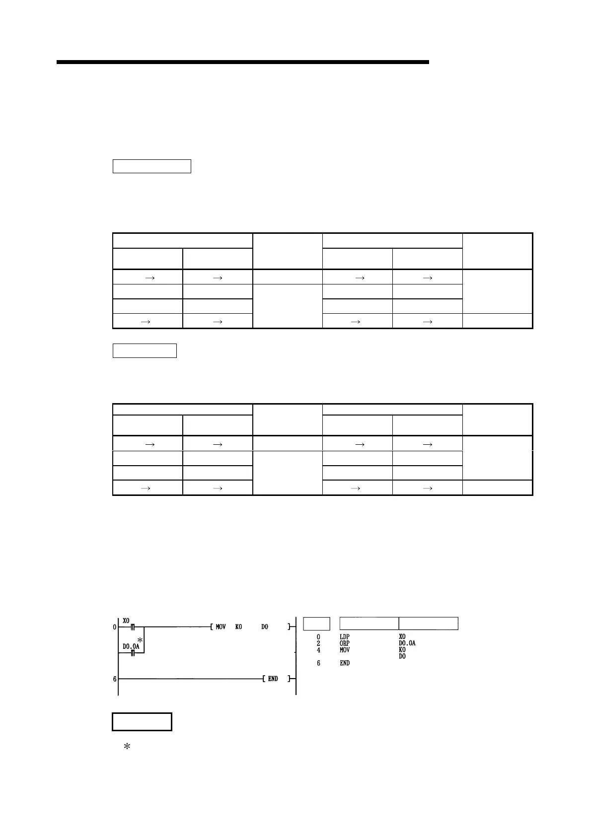
[Program Example]
(1) The following program executes the MOV instruction at input X0, or at the leading edge of b10
(bit 10) of data register D0:
[Ladder Mode] [List Mode]
Steps
Instruction
Device
REMARK
: Word device bit designations are performed in hexadecimal.
Bit b10 of D0 would be D0.0A.
Artisan Technology Group - Quality Instrumentation ... Guaranteed | (888) 88-SOURCE | www.artisantg.com

 Loading...


