2 - 34 2 - 34
MELSEC-Q/QnA
2 INSTRUCTION TABLES
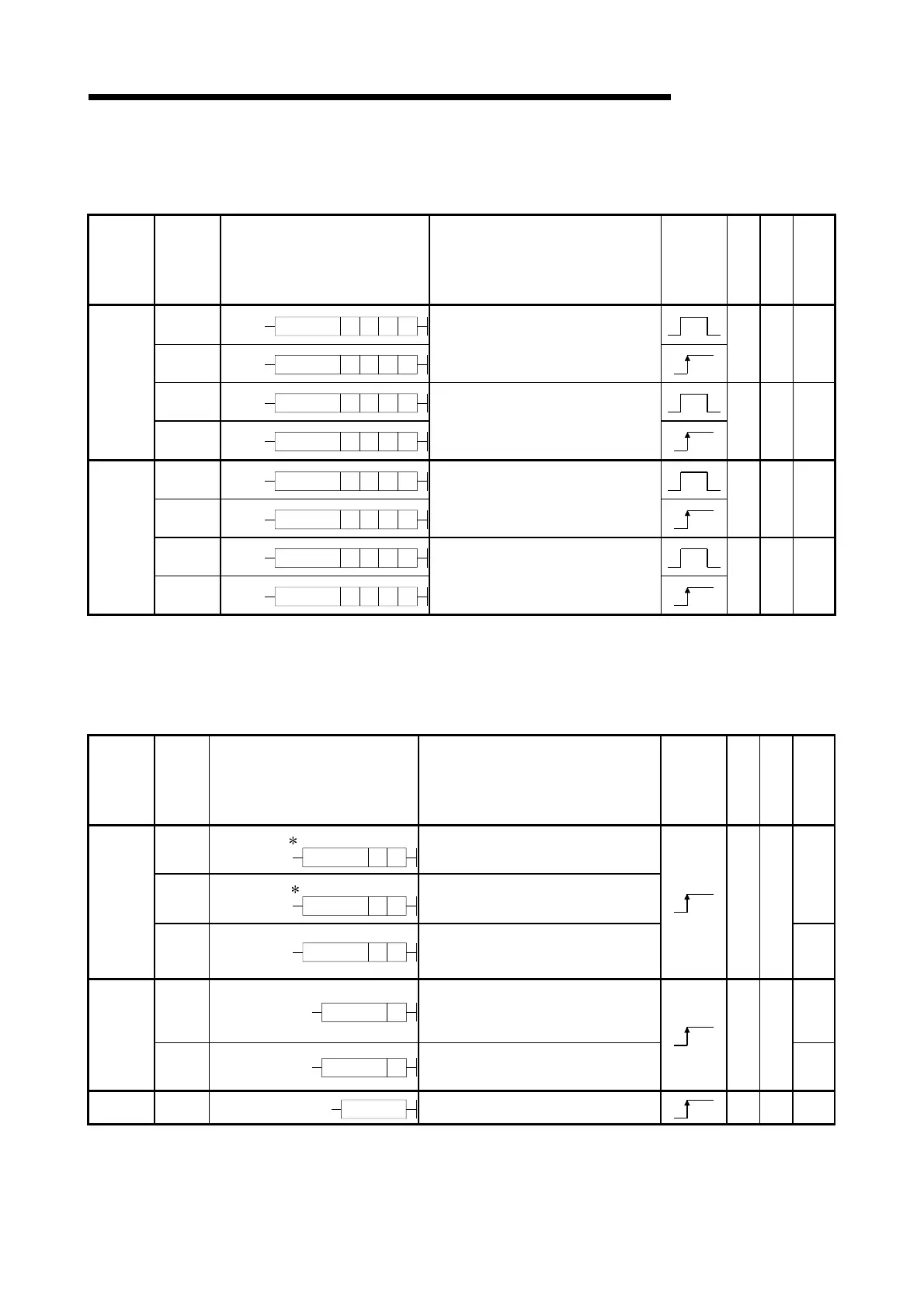
2.5.8 Buffer memory access instructions
Table 2.25 Buffer Memory Access Instructions
Category
Instruction
Symbols
Symbol Processing Details
Execution
Condition
Number of
Basic Steps
Subset
See for
Description
FROM
FROM n3n1 n2 D
FROMP
FROMP n3n1 n2
D
• Reads data in 16-bit units from special
function module
5 7-134
DFRO
DFRO n3n1 n2
D
Data read
DFROP
DFROP n3n1 n2
D
• Reads data in 32-bit units from special
function module
5 7-134
TO
TO n3n1 n2
S
TOP
TOP n3n1 n2
S
• Writes data in 16-bit units to special
function module
5 7-137
DTO
DTO n3n1 n2
S
Data write
DTOP
DTOP n3n1 n2
S
• Writes data in 32-bit units to special
function module
5 7-137
2.5.9 Display instructions
Table 2.26 Display Instructions
Category
Instruction
Symbols
Symbol Processing Details
Execution
Condition
Number of
Basic Steps
Subset
See for
Description
PR
SM701 When OFF
PR SD
• Outputs ASCII code of 8 points (16
characters) from device designated by (S)
to output module.
PR
SM701 When ON
PR SD
• Outputs ASCII code from device
designated by (S) to 00
H
to output module.
7-140
ASCII print
PRC
PRC
S
D
• Converts comments from device
designated by (S) to ASCII code and
outputs to output module.
3
7-143
LED
LED S
• Displays ASCII code of 8 points (16
characters) from the device designated by
(S) at the LED display device on the front
of the CPU.
7-148
Display
LEDC
LEDC S
• Displays the comments from the device
designated by (S) at the LED display
device on the front of the CPU module.
2
7-150
Reset LEDR
LEDR
• Resets annunciator and display unit
display.
1 7-152
Artisan Technology Group - Quality Instrumentation ... Guaranteed | (888) 88-SOURCE | www.artisantg.com

 Loading...


