5 - 33 5 - 33
MELSEC-Q/QnA
5 SEQUENCE INSTRUCTIONS
(2) The table below shows which CPU module features either the LED display device on front of
the CPU module or "USER" LED
Type of LED CPU module Type Name
LED display device Q3A, Q4A, Q4AR
"USER LED" Q2A(S1), Q2AS(S1), Q2ASH(S1), QCPU
(3) If, when the value of SD63 is 16, and annunciator numbers are deleted from SD64 to SD79 by
use of the RST instruction, annunciators whose numbers are not registered in SD64 to SD79
are then turned ON, the numbers of these annunciators will be registered. If all annunciator
numbers from SD64 to SD79 are turned OFF, the LED display device on the front of the CPU
module, or the "USER" LED, will be turned OFF.
[Operations which take place when SD63 is 16]
16
SD63
233
90
700
145
1027
SD64
SD65
SD66
SD78
SD79
16
233
90
700
145
1027
SD64
SD65
SD78
SD79
16
233
700
28
145
30
SD64
SD65
SD66
SD77
SD79
1027
SD78
F90 is reset
F30 turned ON
SD66
The contents of SD63
and SD64 to
SD79 are not changed.
F30, which is ON,
is stored at SD79
The SD67
F number
is stored
[Operation Errors]
(1) There are no operation errors associated with the SET F or RST F instructions.
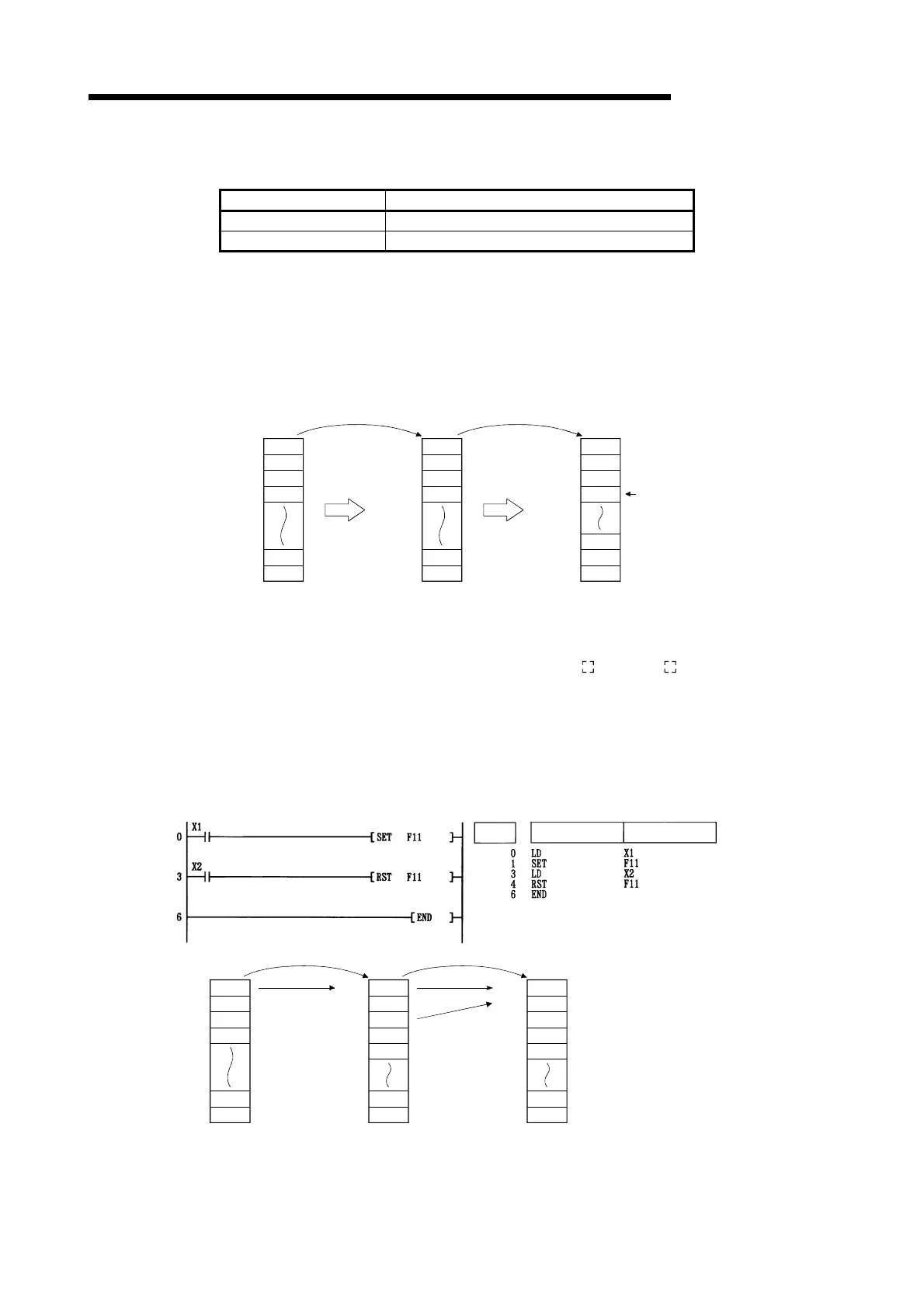
[Program Example]
(1) The following program turns annunciator F11 ON when X1 goes ON, and stores the value 11
at the special register (SD64 to SD79).Further, the program resets annunciator F11 if X2 goes
ON, and deletes the value 11 from the special registers (SD64 to SD79).
[Ladder Mode] [List Mode]
Steps
Instruction
Device
SD63
D64
SD65
SD66
SD78
SD79
SD64
SD65
SD78
SD79
SD64
SD65
SD66
SD79
SD78
When X2 is ONWhen X1 is ON
SD66
Subtracts 1
0
0
0
0
0
0
SD63
SD67
1
11
0
0
0
0
0
SD63
SD67
0
0
0
0
0
0
0
Adds 1
Artisan Technology Group - Quality Instrumentation ... Guaranteed | (888) 88-SOURCE | www.artisantg.com

 Loading...


