EasyManua.ls Logo

Mitsubishi MELSEC QCPU User Manual

Mitsubishi MELSEC QCPU
285 pages
To Next Page IconTo Next Page
To Previous Page IconTo Previous Page
Page #174 background imageLoading...
Page #174 background image
6 - 23 6 - 23
MELSEC-Q/QnA
6 BASIC INSTRUCTIONS
D
-
(1) Subtracts 32-bit BIN data designated by
S1
from 32-bit BIN data designated by
S2
and stores
the result of the subtraction at the device designated by
D
.
123456 (BIN)
+1
567890 (BIN)
b31- -b16 b15- -b0
+1
444434 (BIN)
+1
S1 S2
D
S1 S2
D
-
b31- -b16 b15- -b0 b31- -b16 b15- -b0
(2) The values for
S1
,
S2
, and
D
can be designated at between -2147483648 and 2147483647
(BIN 32 bits).
(3) Judgment of whether the data is positive or negative is made on the basis of the most
significant bit (b31).
• 0 ....... Positive
• 1 ....... Negative
(4) The following will happen when an underflow or overflow is generated in an operation result:
The carry flag in this case does not go ON.
K-2147483648
(H80000000)
K2147483647
(H7FFFFFFF)
-K2
(H2)
-K-2
(HFFFE)
K2147483646........Because b31 is 0,
the value is positive.
K-2147483647.......Because b31 is 1,
the value is negateve.
(HFFFE)
(H7FFFFFFE)
[Operation Errors]
(1) There are no operation errors associated with the +(P) or -(P) instructions.
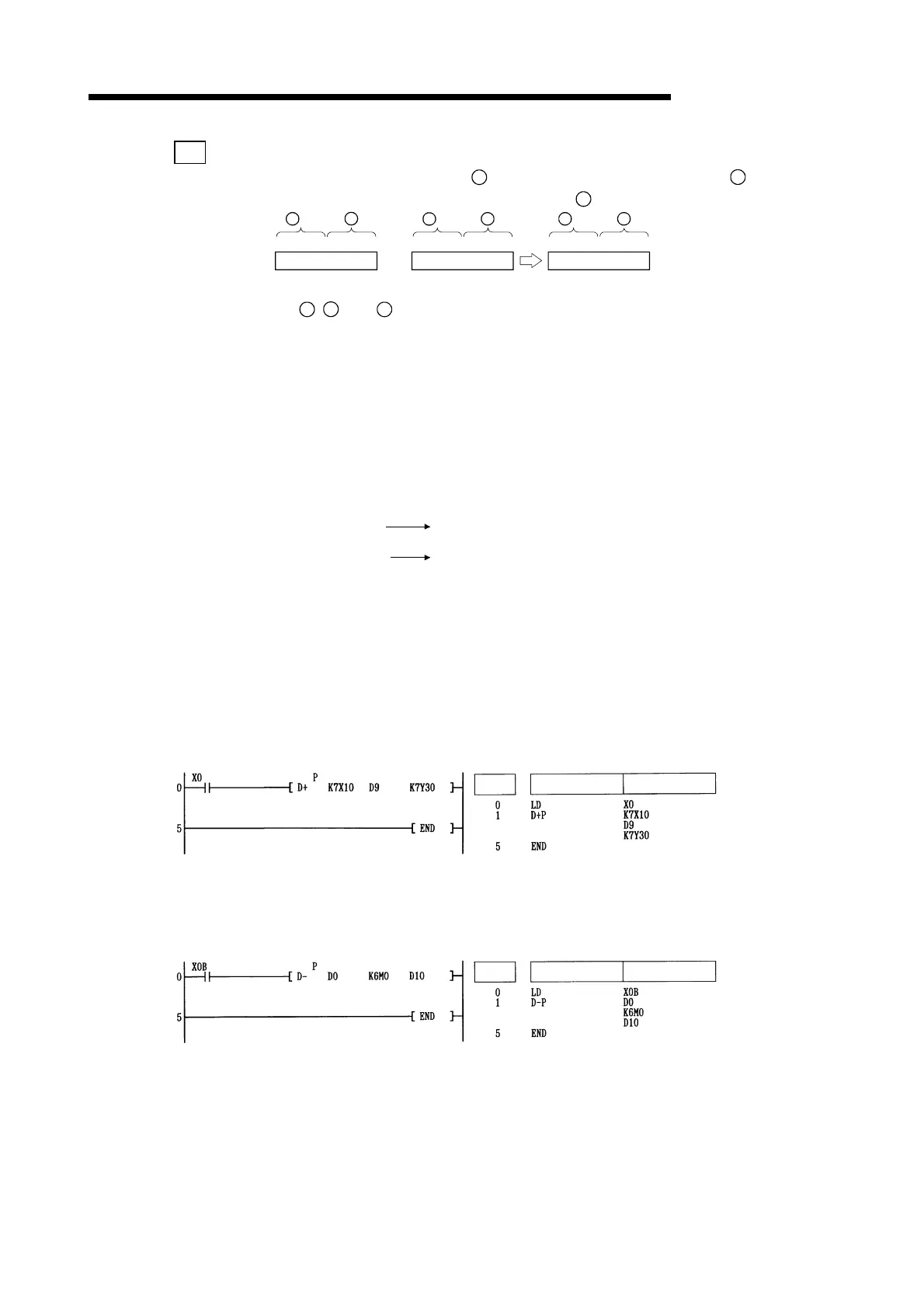
[Program Example]
(1) The following program adds 28-bit data from X10 to X2B to the data at D9 and D10 when X0
goes ON, and outputs the result of the operation to Y30 to Y4B.
[Ladder Mode] [List Mode]
Steps
Instruction
Device
(2) The following program subtracts the data from M0 to M23 from the data at D0 and D1 when
XB goes ON, and stores the result at D10 and D11.
[Ladder Mode] [List Mode]
Steps
Instruction
Device
Artisan Technology Group - Quality Instrumentation ... Guaranteed | (888) 88-SOURCE | www.artisantg.com

Table of Contents

Question and Answer IconNeed help?

Do you have a question about the Mitsubishi MELSEC QCPU and is the answer not in the manual?

Mitsubishi MELSEC QCPU Specifications

General IconGeneral
ModelMELSEC QCPU
SeriesQ Series
CategoryController
MemoryVaries depending on CPU type
Program MemoryVaries depending on CPU type (e.g., 32K steps to 260K steps or more)
Data MemoryVaries depending on CPU type (e.g., 64K words to 512K words)
I/O CapacityUp to 4096 points (varies by model)
Number of I/O PointsUp to 4096 points
CommunicationEthernet
Programming LanguageLadder Logic, Instruction List, SFC, ST, Function Block Diagram
Program CapacityVaries depending on CPU type (e.g., 32K steps to 260K steps or more)
Power Supply24V DC or 100-240V AC (depending on model)
Operating Temperature0°C to 55°C
Storage Temperature-25°C to 75°C
Humidity5 to 95% RH, non-condensing
Shock Resistance147 m/s2, 3 times in X, Y, and Z directions

Summary

SAFETY PRECAUTIONS

REVISIONS

GENERAL DESCRIPTION

Related Programming Manuals

Lists other relevant programming manuals.

Abbreviation and Generic Name

Explains abbreviations and generic names used.

INSTRUCTION TABLES

Types of Instructions

Categorizes the types of CPU module instructions.

How to Read Instruction Tables

Explains the format and conventions of instruction tables.

Sequence Instructions

Instructions for relay control ladders.

Basic Instructions

Common operations like comparison and arithmetic.

Application Instructions

Instructions for specific applications like logical operations.

Instructions for Data Link

Instructions for data communication between stations.

QCPU Instructions

Instructions specific to QCPU modules.

Redundant System Instructions (For Q4ARCPU)

Instructions for redundant system configuration.

CONFIGURATION OF INSTRUCTIONS

Configuration of Instructions

Explains the structure of CPU module instructions.

Designating Data

Describes how to designate data types for instructions.

Index Modification

Explains how to use index registers for indirect addressing.

Indirect Designation

Explains how to use indirect addressing for devices.

Subset Processing

Explains subset processing for performance improvement.

Cautions on Programming (Operation Errors)

Describes programming cautions and potential operation errors.

Conditions for Execution of Instructions

Explains different execution conditions for instructions.

Counting Step Number

Explains how step numbers are calculated for instructions.

Operation when OUT, SET/RST, or PLS/PLF Instructions Use the Same Device

Explains behavior when multiple instructions use the same device.

HOW TO READ INSTRUCTIONS

How to Read Instructions

Explains how to read instruction descriptions.

SEQUENCE INSTRUCTIONS

Contact Instructions

Instructions for operation start and connections.

Connection Instructions

Instructions for connecting ladder blocks.

Operation results push, read, pop (MPS, MRD, MPP)

Instructions for managing operation results.

Timers (OUT T, OUTH T)

Instructions for low and high speed timers.

Counters (OUT C)

Instructions for up/down counters.

Resetting devices (except for annunciators) (RST)

Instruction to reset devices OFF.

Leading edge and trailing edge output (PLS, PLF)

Instructions for pulse output on leading/trailing edges.

Shift Instruction

Instructions for shifting bit devices.

Master Control Instructions

Instructions for master control of program execution.

Termination Instructions

Instructions to terminate program execution.

Other Instructions

Miscellaneous instructions.

BASIC INSTRUCTIONS

Comparison Operation Instruction

Instructions for comparing data.

Arithmetic Operation Instructions

Instructions for addition, subtraction, multiplication, division.

Data Conversion Instructions

Instructions for converting data formats.

Data Transfer Instructions

Instructions for moving data.

Program Execution Control Instructions

Instructions to control program execution flow.

Other Convenient Instructions

Various useful instructions.

APPENDICES

APPENDIX1 OPERATION PROCESSING TIME

Details processing times for various CPU modules.

APPENDIX 2 COMPARISON OF PERFORMANCE BETWEEN CPUs

Compares performance across different CPU types.

APPENDIX 3 SPECIAL RELAY LIST

Lists and explains special relays.

APPENDIX 4 SPECIAL REGISTER LIST

Lists and explains special registers.

APPENDIX 5 APPLICATION PROGRAM EXAMPLES

Provides examples of application programs.

Related product manuals