6 - 123 6 - 123
MELSEC-Q/QnA
6 BASIC INSTRUCTIONS
The direction of rotation is judged by whether the B phase pulse is at its leading or trailing
edge when the A phase pulse is ON:
• When the B phase is at the leading edge : Forward rotation (clockwise rotation)
• When the B phase is at the trailing edge: Reverse rotation (counterclockwise rotation)
(6)
D
+2 is the 0 point detection output signal that goes ON when item number 0 has arrived at
the No. 0 station.
When the device designated by
D
+2 goes ON while the ROTC instruction is being executed,
S
+0 is cleared.
It is best to perform this clear operation first, then to begin near path rotation with the ROTC
instruction.
(7) The data from
D
+3 to
D
+7 consists of output signals needed to control the table's operation.
The output signal of one of the devices from
D
+3 to
D
+7 will go ON in response to the
execution results of the ROTC instruction.
(8) If operation results immediately prior to the ROTC instruction are OFF, all signals from
D
+3 to
D
+7 will be OFF without near path rotation controls having been performed.
(9) The ROTC instruction can be used only one time in all programs where it is executed.
Attempts to use it more than one time will result in inaccurate operations.
(10) No processing is performed when the value of
S
+0 to
S
+2, or the value of n2 is greater than
n1.
[Operation Errors]
(1) There are no errors associated with the ROTC instruction.
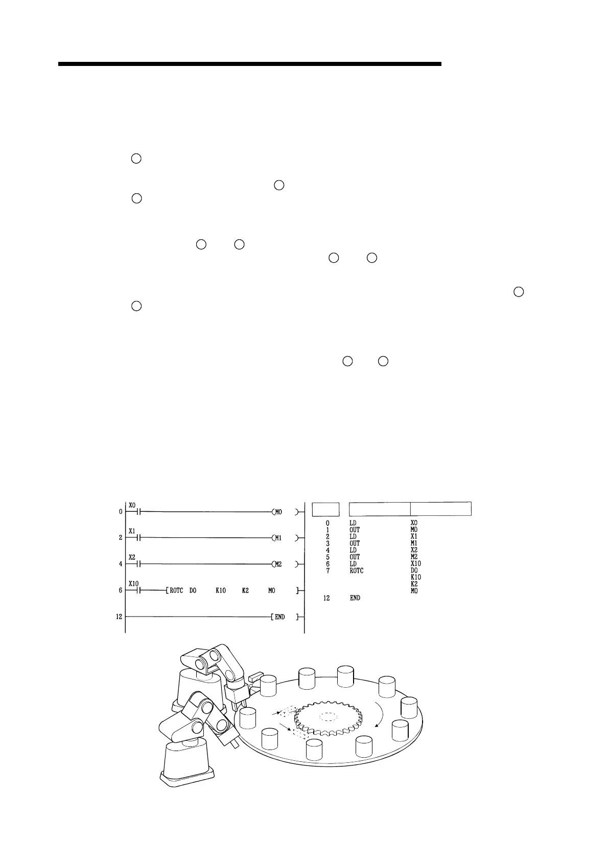
[Program Example]
(1) The following program deposits the item at section D2 on a 10-division rotary table at the
station at section D1, and the two sections ahead and behind this determine the rotation
direction and control speed of the motor when the table is being rotated at low speed.
[Ladder Mode] [List Mode]
Steps
Instruction
Device
Station No. 0
Station No. 1
X000
X001
Part
8
7
6
5
4
3
2
1
0
9
0 point detection
X002
Rotary table
Detection
switch
Forward
rotation
Artisan Technology Group - Quality Instrumentation ... Guaranteed | (888) 88-SOURCE | www.artisantg.com

 Loading...


