1. FUNCTIONS AND CONFIGURATION
1 - 4
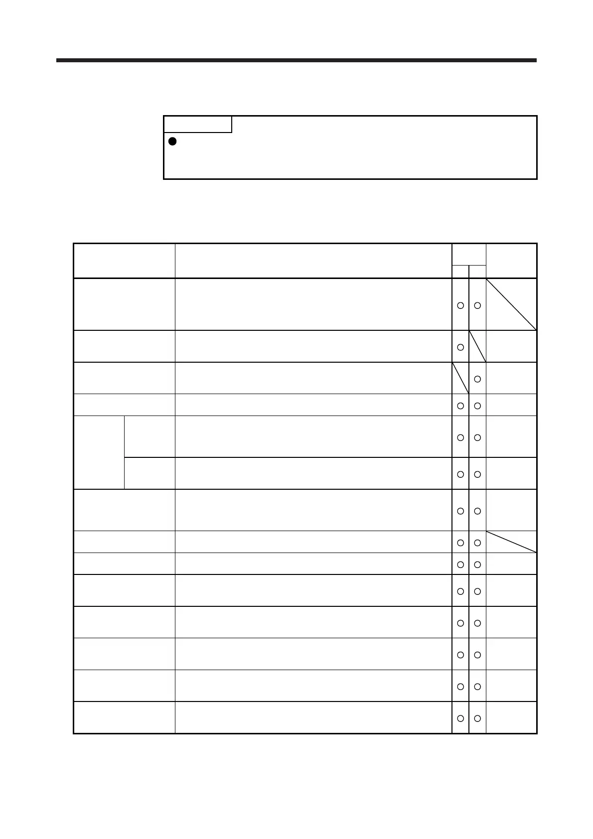
1.3 Function list
POINT
The symbols in the control mode column mean as follows.
CP: Positioning mode (point table method)
CL: Positioning mode (program method)
The following table lists the functions of this servo. For details of the functions, refer to each section
indicated in the detailed explanation field. "MR-JE-_A" means "MR-JE-_ A Servo Amplifier Instruction
Manual".
Function Description
Control
mode
Detailed
explanation
CP CL
Model adaptive control
This function achieves a high response and stable control following the ideal
model. The two-degrees-of-freedom model adaptive control enables you to
set a response to the command and response to the disturbance separately.
Additionally, this function can be disabled. To disable this function, refer to
section 7.4 of "MR-JE-A_ Servo Amplifier Instruction Manual".
Positioning mode (point
table method)
Set 1 to 31 point tables in advance, and select any point table to perform
operation in accordance with the set values. To select point tables, use
external input signals or communication function.
Chapter 4
Positioning mode
(program method)
Set 1 to 16 programs in advance and select any program to perform
operation in accordance with the programs. To select programs, use
external input signals or communication function.
Chapter 5
Roll feed display function
Positions based on specified travel distance from a status display "0" of
current/command positions at start.
Section 4.5
Mark
detection
Current
position
latch
function
When the mark detection signal turns on, the current position is latched. The
latched data can be read with communication commands.
Section
6.6.2
Interrupt
positioning
function
When MSD (Mark detection) turns on, this function converts the remaining
distance to the travel distance set in [Pr. PT30] and [Pr. PT31] (Mark sensor
stop travel distance).
Section
6.2.3
Home position return
Dog type/count type/data setting type/stopper type/home position
ignorance/dog type rear end reference/count type front end reference/dog
cradle type/dog type last Z-phase reference/dog type Z-phase
reference/dogless Z-phase reference
Section 4.4
Section 5.4
High-resolution encoder
High-resolution encoder of 131072 pulses/rev is used as the encoder of the
rotary servo motor compatible with the MELSERVO-JE series.
Gain switching function
You can switch gains during rotation/stop, and can use input devices to
switch gains during operation.
MR-JE-_A
Section 7.2
Advanced vibration
suppression control II
This function suppresses vibration at an arm end or residual vibration.
MR-JE-_A
Section
7.1.5
Machine resonance
suppression filter
This filter function (notch filter) decreases the gain of the specific frequency
to suppress the resonance of the mechanical system.
MR-JE-_A
Section
7.1.1
Shaft resonance
suppression filter
When a load is mounted to the servo motor shaft, resonance by shaft torsion
during driving may generate a mechanical vibration at high frequency. The
shaft resonance suppression filter suppresses the vibration.
MR-JE-_A
Section
7.1.3
Adaptive filter II
The servo amplifier detects mechanical resonance and sets filter
characteristics automatically to suppress mechanical vibration.
MR-JE-_A
Section
7.1.2
Low-pass filter
Suppresses high-frequency resonance which occurs as the servo system
response is increased.
MR-JE-_A
Section
7.1.4

 Loading...