3. DISPLAY AND OPERATION SECTIONS
3 - 7
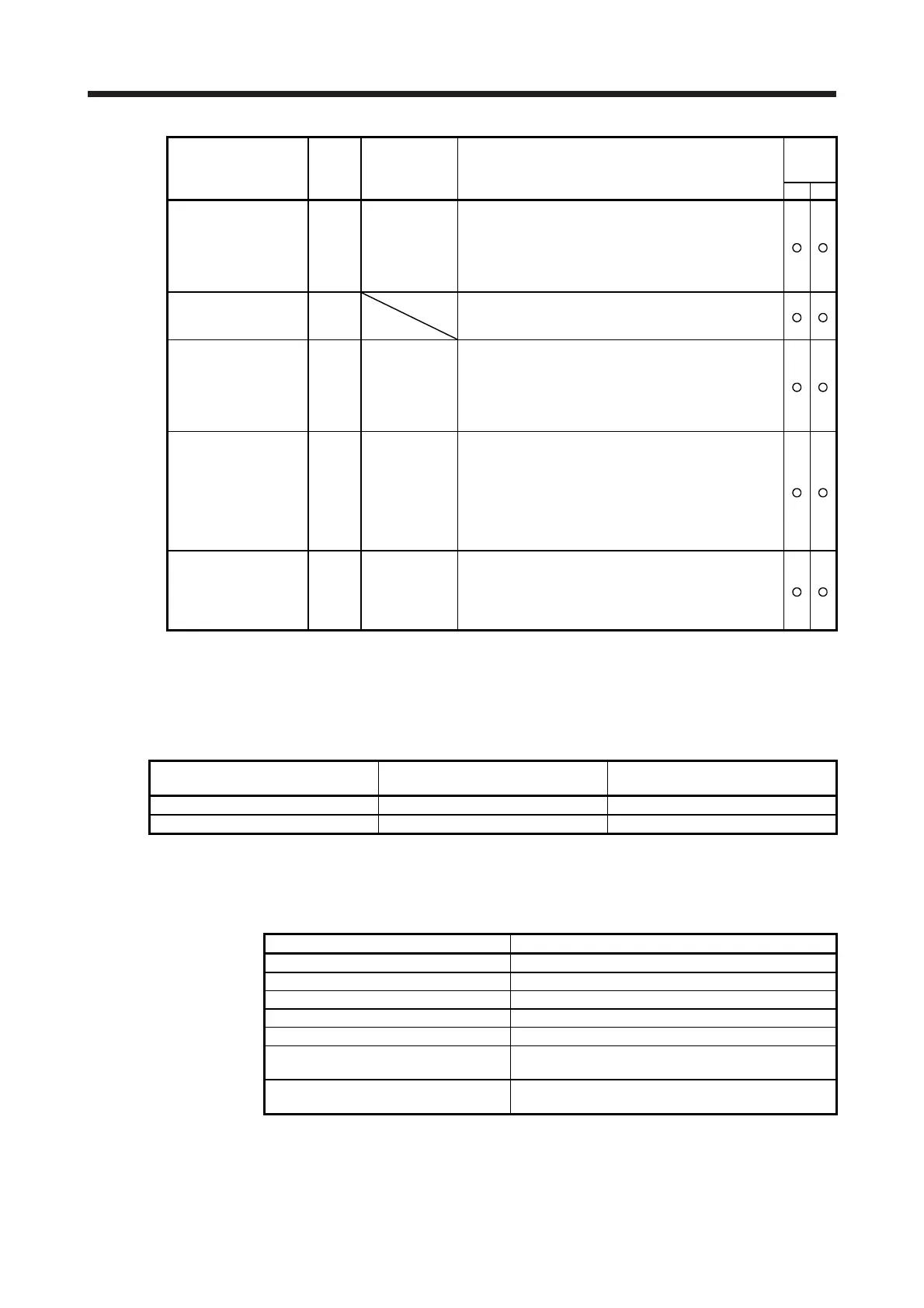
Status display Symbol Unit Description
Control
mode
(Note 1)
CP CL
Cam axis feed current
value
CCMd
10
STM
μm
10
(STM-4)
inch
10
-3
degree
pulse
(Note 2)
A feed current value during the cam axis control is displayed.
The values in excess of ±99999 can be counted. However, the
counter shows only the lower five digits of the actual value since
the servo amplifier display is five digits.
When the simple cam function is disabled, 0 is always displayed.
Refer to section 6.1.8 for detecting point.
Cam No. in execution Cno
Cam No. in execution is displayed.
When the simple cam function is disabled, 0 is always displayed.
Refer to section 6.1.8 for detecting point.
Cam stroke amount in
execution
CSTK
10
STM
μm
10
(STM-4)
inch
10
-3
degree
pulse
(Note 2)
Cam stroke amount in execution is displayed.
The values in excess of ±99999 can be counted. However, the
counter shows only the lower five digits of the actual value since
the servo amplifier display is five digits.
When the simple cam function is disabled, 0 is always displayed.
Refer to section 6.1.8 for detecting point.
Main axis current value MCMd
10
STM
μm
10
(STM-4)
inch
10
-3
degree
pulse
(Note 3)
A current value of the input axis (synchronous encoder axis or
servo input axis) is displayed. Unit is increment of input axis
position.
The values in excess of ±99999 can be counted. However, the
counter shows only the lower five digits of the actual value since
the servo amplifier display is five digits.
When the simple cam function is disabled, 0 is always displayed.
Refer to section 6.1.8 for detecting point.
Main axis one cycle
current value
MCyC
10
STM
μm
10
(STM-4)
inch
10
-3
degree
pulse
(Note 3)
The input travel distance of the input axis in a range between 0
and (cam axis one cycle length setting - 1) is displayed. Unit is
an increment of cam axis one cycle.
When the simple cam function is disabled, 0 is always displayed.
Refer to section 6.1.8 for detecting point.
Note 1. CP: Positioning mode (point table method)
CL: Positioning mode (program method)
2. The unit can be selected from μm/inch/degree/pulse with [Pr. PT01].
3. Depending on the setting of [Cam control data No. 30 Main shaft input axis selection], the parameters used to
set the unit and feed length multiplication will change as follows. For details of each parameter, refer to section
6.1.7 (3) and 7.2.7.
Setting of [Cam control data No. 30] Parameter for the unit setting
Parameter for the feed length
multiplication setting
"0" or "1" [Pr. PT01] [Pr. PT03]
"2" [Cam control data No. 14] [Cam control data No. 14]
(3) Changing the status display screen
The status display on the servo amplifier at power-on can be changed with [Pr. PC36]. The status
displayed by default varies depending on the control mode as follows:
Control mode Status display
Position Cumulative feedback pulses
Position/speed Cumulative feedback pulses/servo motor speed
Speed Servo motor speed
Speed/torque Servo motor speed/analog torque command voltage
Torque Analog torque command voltage
Torque/position
Analog torque command voltage/cumulative feedback
pulses
Positioning (point table method/program
method)
Current position

 Loading...