3-75
Extended serial interface
3 Controller
Three cards can be installed on one controller.
(The communication line of maximum 6 channels cable connected.)
Table 3-31 : Difference by the card version
△ : The option slot 1(OPT1) or 2(OPT2) is available. (Up to two boards can be used.)
○ : Every option slot is available. (Up to three boards can be used.)
(*1) Operation is compatible with RZ581A.
■ Functions
(1) Controller communication function
・ This function allows to update and download programs as well as to monitor various statuses.
・The personal computer support software (sold separately) is available as a robot controller programming support
tool.
Refer to (9), Page 84, "(12) Personal computer support software/Personal computer support software mini"
of details.
(2) Data link function
・ The data link function allows to link numerical values and position data between robot programs and a personal
computer using the MELFA-BASIC IV language (OPEN/PRINT/INPUT instruction).
・ Data can be exchanged one to one by specifying the COM number at the communication open destination.
■ Pin assignment
(1) RS-232C pin assignment
Refer to Page 72, "(7) Personal computer cable".
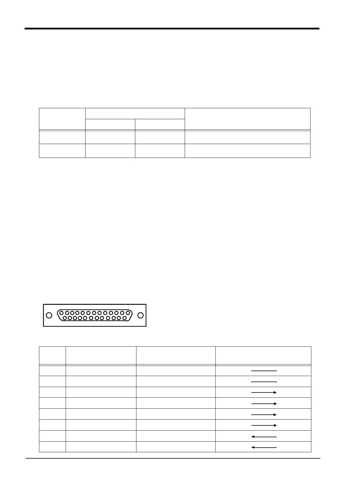
(2) RS-422 pin assignment
Fig.3-25 : D-SUB25 Pin Female Connector (RZ581 Board Side)
Note2)Nonprocedural: Nonprocedural protocol with the personal computer support software
Procedural: Procedural protocol with the personal computer support software
Data link: Nonprocedural (ASCII data) protocol for data link between robot programs and a personalcom
-
puter/PLC/vision sensor, etc.
Type
Supporting software version
Rmarks
From the E1 to K6 K7 or later
RZ581A or earlier
△ △
Unrelated to the software version, up to two boards can be
used. (Slot 1(OPY1)/ 2(OPT2))
RZ581B or later
△ (*1) ○
Up to three boards can be used, by using with version K7 or
later. (Slot 1(OPY1)/ 2(OPT2)/ 3(OPT3))
Pin no. Abbreviated signal name Signal name
Signal direction
2A-RZ581 ⇔ Device on other end
1 FG Frame ground
7, 9 SG Signal ground
13 TXD+(SDA) Transmission data (+)
25 TXD-(SDB) Transmission data (-)
11 DTR+(RSA) Terminal ready (+)
23 DTR-(RSB) Terminal ready (-)
12 RXD+(RDA) Reception data (+)
24 RXD-(RDB) Reception data (-)
1
13
25
14
 Loading...


