7-32
Chapter 7 ASSEMBLY OF BASIC ENGINE
5.14.2 Fuel Injection Timing - Check
(1) Turn the crankshaft in normal direction, and stop the
turning when the No. 1 cylinder is positioned at approx
10° before the specified fuel injection timing.
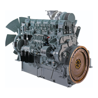
Check that the "0" stamped line of fuel injection pump
flywheel indicates before the pointer.
Note: In this condition, the clearances of inlet and exhaust
valves are as specified, and valves are not pushed
down.
In case of the exhaust stroke top dead center, valves are
pushed down.
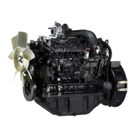
(2) Turn the crankshaft to the normal direction progres-
sively, align the fuel injection timing mark on damper
with engine pointer.
If the "0" line mark of fuel injection pump flywheel
aligns with pointer, the fuel injection timing is adjusted
to the specified timing.
If the "0" line mark does not align with pointer, adjust
the fuel injection timing.
TDC for Cylinder No.1 - Positioning
Fuel Injection Timing - Check
5.14.3 Fuel Injection Timing - Adjust
(1) Turn the crankshaft to the normal direction progres-
sively, align the fuel injection timing mark on damper
with engine pointer.
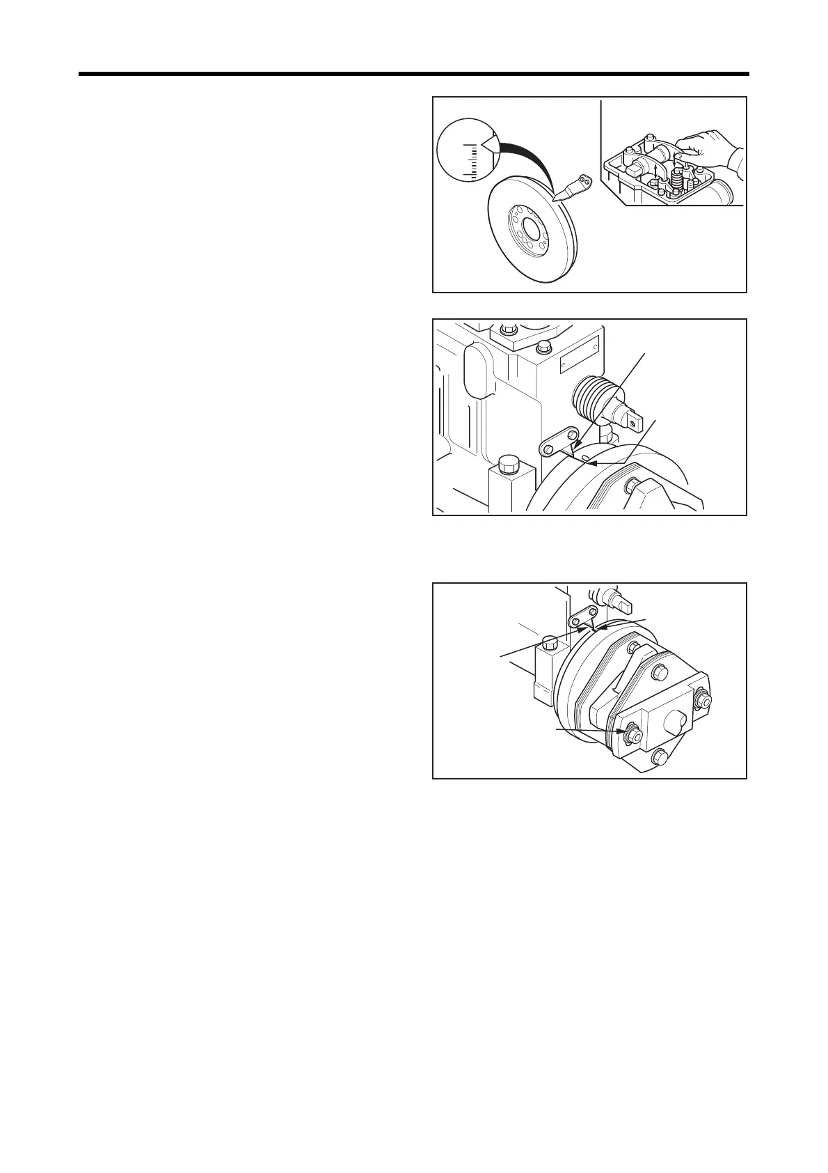
(2) Loosen the bolts (long) of driving coupling, and rotate
the fuel injection pump only. Adjust the "0" line mark
to pointer, then tighten the bolts (long.)
(3) From the specified fuel injection timing, turn the crank-
shaft in the reverse direction by approx 10°.
(4) Turning the crankshaft to the normal direction progres-
sively again, align the line mark of fuel injection timing
with the pointer.
In this condition, check the "0" line mark of fuel injec-
tion pump flywheel aligns with the pointer.
Repeat the step (2) until the proper alignment is made.
Fuel Injection Timing - Adjust
Check forcompression
top dead center
Pointer
Line mark on
the flywheel
Pointer
Line mark on
flywheel
Bolt (long)
M14:118 ± 5 N·m
{12 ± 0.5 kgf·m}
[87 ± 3.7 lbf·ft]
2-time tightening method
M12:108 ± 5 N·m
{11 ± 0.5 kgf·m}
[80 ± 3.7 lbf·ft]
2-time tightening method

 Loading...