Chapter Two: Installation Setup
11
Mounting Instructions
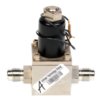
The valve may be installed in any position, although base vertically down is recommended.
Although ¼” O.D. tubing connections are generally adequate to support the weight of the valve,
two 10-24 mounting holes permit base mounting. A 0.62” minimum clearance hole in a
mounting plate should be provided to allow the valve orifice to be adjusted or replaced without
disconnecting the valve.
Tubing lengths should be kept short throughout the flow control loop and restrictions and bends
eliminated wherever possible.
Always couple the 248 valve with the minimum practical length of straight ¼” tubing to the
upstream flow sensor to achieve stable flow control.
Cables
To connect the 248 valve to a Type 250D-E or 1250 controller, use cable CB251-2-10.
To connect the 248 valve to a Type 250A-C, or 260 controller, use cable CB251-1-10.
Note
1. Overall metal, braided shielded cables are required to meet CE Mark
specifications.
2. To order a metal braided, shielded cable, add an “S” after the cable
type designation. For example, to order a standard cable to connect
the 248 valve to a 250D-E controller, use part number CB251-2-10;
for a metal, braided, shielded cable use part number CB251S-2-10
The cable assembly is not considered part of the valve; it is furnished whenever a flow control
system is ordered.