Chapter Four: Maintenance General Information
15
Chapter Four: Maintenance
General Information
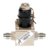
Periodically check for wear on the cables and inspect the valve for visible signs of damage.
Orifice Adjustment and Replacement
All 248 valve seals are 100% leak checked at the factory prior to shipment. With no power
applied, the valve should have no measurable leakage or flow when the valve is positioned
vertically, base down, and 1 atmosphere differential pressure is applied.
Should unacceptable leakage exist because of different operating conditions or normal wear,
adjustment is achieved by turning the Orifice Assembly Adjustment Screw in the base clockwise.
Refer to Figure 4, page 16, as needed.
Note
• Turn the orifice 5° to 10° at a time, each time observing a change in
leakage.
• Turn the orifice an additional 10° to 15° beyond the threshold of
acceptable leakage. Excessive clockwise adjustment may reduce
maximum flow control or impair control response.
• If leakage cannot be corrected by adjusting the Orifice Assembly, the
problem is one of the following:
1. Leaky seat - replace the Armature/Plug Assembly
2. Leaky Orifice Assembly Seal - replace the seals or assembly
3. Scored, pitted Body - inspect, replace as required
• ALWAYS disconnect the valve from its controller when adjusting for
orifice leakage as valve bias misadjustment (refer to controller
manual) may hold the valve partially open.
Caution
NEVER screw the Orifice Assembly hard up to the Armature/Plug
Assembly. Damage requiring replacement of either or both assemblies
will result.