6
1
2
3
4
5
6
7
8
9
10
11
12
13
14
15
16
17
X1
GND
+24VDC in
GND
+ 5V / 150mA
+12V / 150mA
0 - 1 V
0 - 10 V
0 - xxx V
GND
+/- 10V
+
Out (K2, Min )
Out (K3, Max)
Out (K4, Zero)
Com +
20 mA Analogue Out
Analogue Out
Optional
Com + 10-30V
Out
max. 50mA
NC
NO
C
NC
NO
C
NC
NO
C
Min ( K2 )
Max ( K3 )
Zero ( K4 )
Optional
L1
L2
N
230 VAC
115 VAC
N
X2
X4
X5
X6
50R
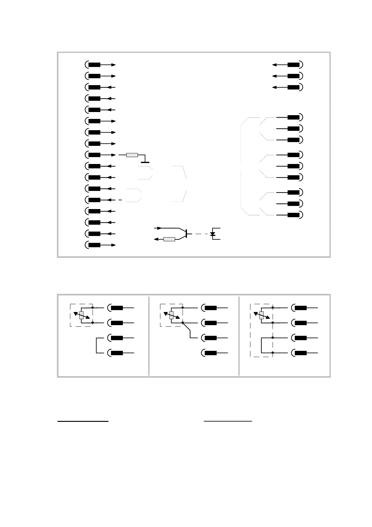
Für Geräte in Pt100- Ausführung gelten die
folgenden Anschlußbilder.
Units with Pt100 version use the following
sensor connections.
Pt100
8
3
6
9
2- Leiter- Anschluß
2- wire connection
Pt100
3- Leiter- Anschluß
3- wire connection
Pt100
4- Leiter- Anschluß
4- wire connection
8
3
6
9
8
3
6
9
Der Meßbereich von -50° bis +400° ist per
Software linearisiert.
The measuring range from -50° to +400°is
fully linearised by software.
2. Blockschaltbild
2. Block Diagram
Das nachfolgende Blockschaltbild zeigt die
technische Struktur der Geräte. Gestrichelt
gezeichnete Teile sind optionell. Die Anga-
ben „Pxx“ kennzeichnen die zugehörigen
Parameter.
The subsequent diagram explains the
technical structure of AX units. Parts printed
in dotted lines are optional. Indications like
„Pxx“ show the apropriate parameter
number.

 Loading...


