Chapter Seven: Troubleshooting How To Ad
ust the Valve Preload (MFC onl
)
51
1. Disconnect the cable to power down the unit.
2. Use a
3
/
32
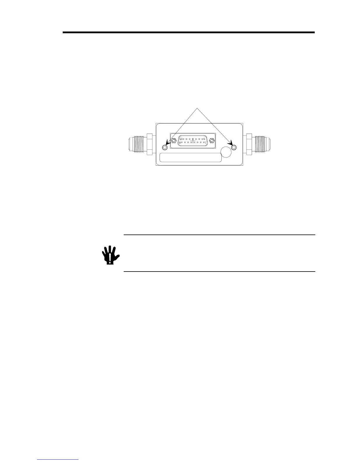
” allen wrench to remove the enclosure retaining screws. Remove the enclosure
cover.
Figure 8 shows the location of the retaining screws.
Retainin
Screws
Figure 8: Location of the Retaining Screws
3. Reconnect the cable to power up the unit.
4. Set your processing system to supply the MFC with a non-hazardous gas (Ar, N
2
, or He)
and purge thoroughly.
Warning
You MUST use a “safe” gas while making any valve
adjustments to safeguard against inadvertent exposure to
any toxic or hazardous gas. DO NOT adjust the valve while a
hazardous or toxic gas is flowing through the MFC.
If you cannot use a “safe” gas within your processing system, remove the MFC and
purge the unit as required by your corporate policies and any appropriate safety
procedures. Once the unit is purged properly perform the valve adjustment outside of the
system, maintaining the same orientation (flow direction) as used in the processing
system.
Choose a “safe” gas with a similar molecular weight as the actual process gas. More
specifically, helium is best used as a substitute for other very light gases such as
hydrogen.
 Loading...