VENTICELL 22
The air lter is a part of the optional accessories,
it is installed when cooling by forced air
circulation. Class of the HEPA lter according to
DIN 24 184 is S, according to EUROVENT it is
EU 13.
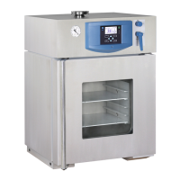
Insert the nuts for xing of the HEPA lter into
four rectangular holes in the rear cover. Put two
rubber rings on the edge of the suction chimney.
Put the pipe of HEPA lter on the chimney.
During the putting on, please, take care of the
fact so the rings would not be shifted by the pipe
of HEPA lter away, but the rings must be forced
into the gap between the pipes. Please, x the
put on HEPA lter with four screws.
If the HEPA lter is equipped with a fan, insert its
socket plug into the socket for its energy supply.
HEPA lter assembly to the apparatus of
size 22:
- insert the supplied nuts into the holes in the
rear wall (1/13)
- put 2 pcs of O-rings on the edge of the suction
chimney
- put the air conduit on the suction chimney (2)
- put 2 pcs of O-rings on the air conduct
- put the unit of HEPA lter on the air conduct
and position it into a proper position
- x it with a screw (1/12) and washer (1/15) to
the rear wall
- connect the fan connector into the socket in
the rear wall (only in case of the overpressure
HEPA lter).
Instructions for use
LSI_K_np_en 1206_mmm_V2.08_B2V 29
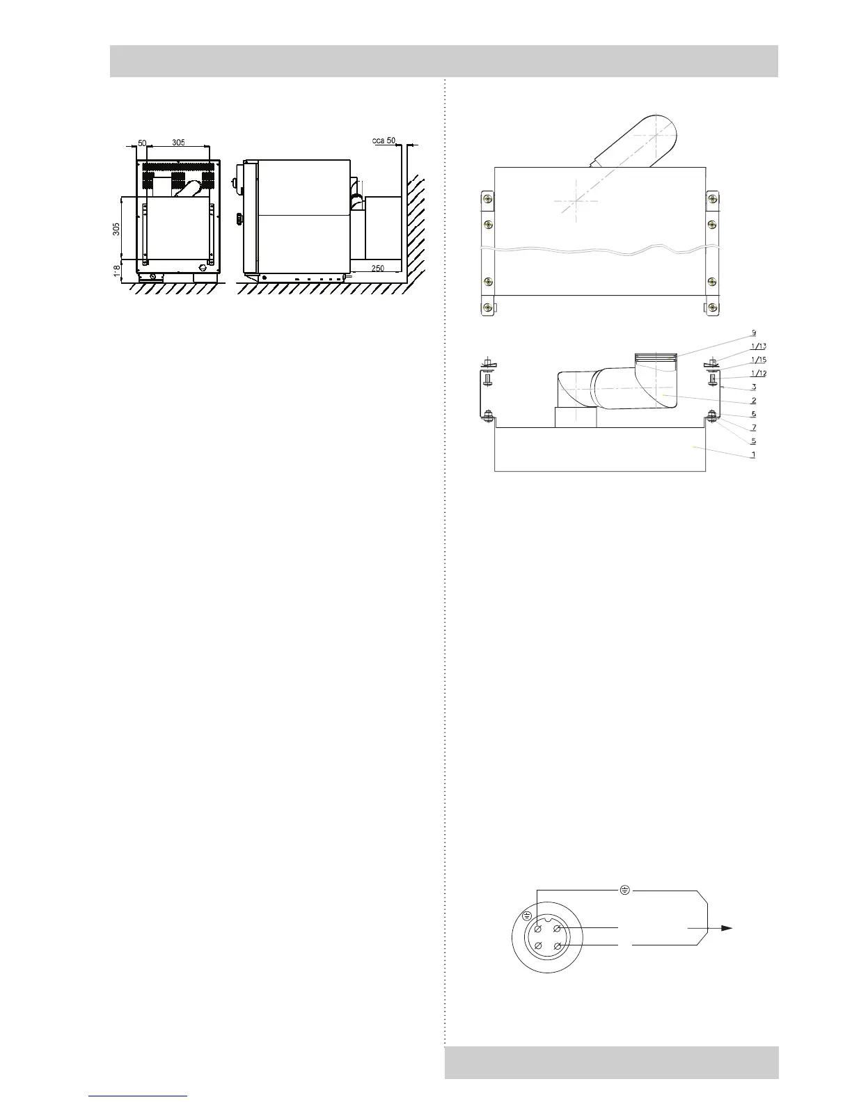
1
2
3
N
L1 (230V/1A)
VIDLICE
K PRÍSTROJI
Plug
to the
eQuiPment
Is lead to the connector in the rear foot, the
voltage up to 24 V/ 1A can be connected to it
Serves for remote alarm (in Anglo-Saxon
countries marked as BMS relay Building
Management System relay) – i.e. the information
on the failure is transmitted by a long-distance
line, interrupted by the built-in relay of a potential-
free contact, into a room that is distant from the
place the temperature cabinet is installed in.
The relay switches on in all failure conditions
reported on the display.
The socket is placed (only for INCUCELL V)
in the chamber on the side wall. Details of the
switching control see par. Basic setting of the
units – Service 06, connection and other details
are shown in the following diagram and text.
Connection wiring beetween plug and built-in
equipment
 Loading...