29
❑ Kwik Bond Thin C/A
❑ # 1 Phillips Head Screwdriver
❑ Wire Cutters
❑ Needle Nose Pliers
❑ Excel Modeling Knife
❑ Electric Drill
❑ 1/16" & 5/64" Drill Bits
❑ Ernst Airplane Stand
❑ Ruler
❑ Pencil
❑ Masking Tape
❑ Global Heat Gun
YOU'LL NEED THE FOLLOWING PARTS FROM THE KIT:
YOU'LL NEED THE FOLLOWING TOOLS AND SUPPLIES:
SECTION 15: ELEVATOR CONTROL SYSTEM INSTALLATION
❑ (2) 6-3/8" Threaded Wires w/90º Bends
❑ (2) Nylon Control Horns w/Backplates
❑ (2) Nylon Clevises
❑ (2) Nylon 90º Snap-Keepers
❑ (4) M2 x 12mm Machine Screws
STEP 1: INSTALLING THE ELEVATOR SERVOS
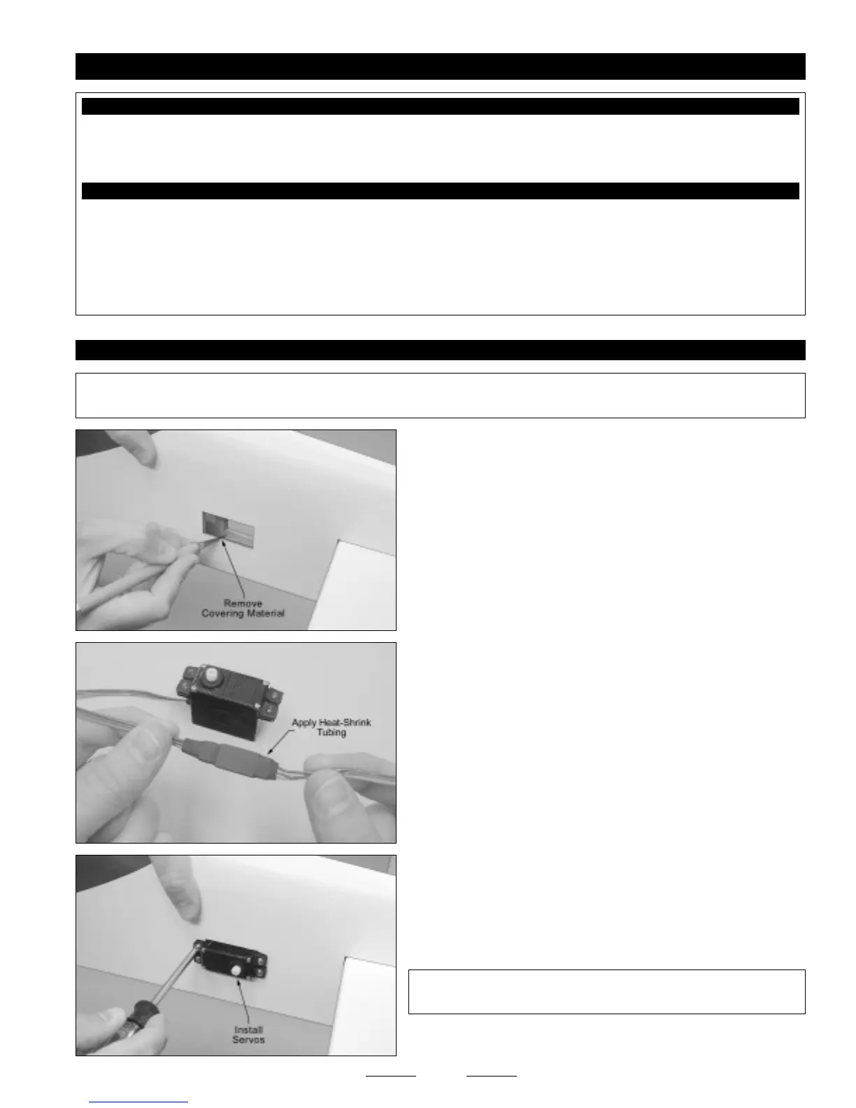
❑ Using a modeling knife, cut away and remove the covering material
from over the elevator servo mounting hole in each side of the fuselage.
☞
Both holes are located 12" in front of the rudder hinge line. The
hole on the right side of the fuselage is located 1" up from the bottom of
the fuselage and the hole on the left side of the fuselage is located
1-3/4" up from the bottom of the fuselage.
✦✦
✦✦
✦IMPORTANT
✦✦
✦✦
✦ The elevator control system uses two separate elevator servos and pushrod assemblies, one on each side of
the fuselage. The servos are installed offset, so that no servo reverser is necessary.
❑ Install the rubber grommets and brass collets onto both elevator
servos, making sure to install the collets with the flanges toward the
bottom of the servos.
❑ Plug one 12" servo extension onto each of the elevator servo leads.
❑ To prevent the plugs from pulling apart during assembly, or worse,
during flight, secure the plugs together, using a short piece of 3/8"
diameter heat-shrink tubing. Use a heat gun to shrink the tubing tight.
❑ Run the servo extension leads through the fuselage and into the radio
compartment, then install the elevator servos into the mounting holes,
making sure to drill 1/16" diameter pilot holes for the mounting screws.
✦✦
✦✦
✦IMPORTANT
✦✦
✦✦
✦ Both servo output shafts should be toward the back
of the fuselage, as shown.
Continued On Next Page
☛☛
☛☛
☛