10
8-504.11
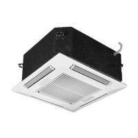
INSTALLATION
Piping Installation
Piping Installation – DX and Heat Pump Units
CAUTION
Do not overcharge the refrigeration system. This can lead
to elevated compressor discharge pressure and possibly
ooding to the compressor with liquid.
ATTENTION
Ne surchargez pas le système de réfrigération. Cela peut
entraîner une pression d’évacuation élevée du compresseur
et possiblement son inondation.
IMPORTANT
1. Units with DX evaporator coils (refer to model
nomenclature) contain the refrigerant R-410A. Review the
R-410A Material Safety Data Sheet (MSDS) for hazards
and rst aid measures.
2. Refrigerant charging should only be carried out by an EPA-
certied air conditioning contractor.
3. Units with DX coils (refer to the model nomenclature) are
partial units, complying with partial unit requirements of UL
60335-2-40, and must only be connected to other units that
have been conrmed as complying to corresponding partial
unit requirements of UL 60335-2-40/CSA C22.2 No. 60335-
2-40, or UL 1995/CSA C22.2 No. 236.
IMPORTANT
1. Les unités munies de serpentins évaporateurs DX
(reportez-vous à la nomenclature du modèle) contiennent
du uide frigorigène R-410A. Pour les dangers et les
mesures de premiers soins, consultez la che signalétique
du R-410A.
2. L’ajout de frigorigène doit être coné à un spécialiste de
la climatisation certié par l’agence de la protection de
l’environnement (EPA) du gouvernement américain.
3. Les unités munies de serpentins DX (reportez-vous à la
nomenclature du modèle) sont des unités partielles, se
conformant aux exigences relatives aux unités partielles
UL 60335-2-40, et ne doivent être reliées qu’à d’autres
unités qui sont conrmées comme étant conformes aux
exigences correspondantes des unités partielles UL
60335-2-40/CSA C22.2 Nº 60335-2-40 ou UL 1995/CSA
C22.2 Nº 236.
Note: Note: R-410A refrigerant is the only approved refrigerant
for this system.
1. The unit should be piped up in accordance with good
refrigeration and/or plumbing practices.
2. The outdoor condensing unit must be connected to the
indoor unit coil using eld supplied refrigerant grade (ACR)
copper tubing that is internally clean and dry. Units should
be installed only with the tubing sizes for the approved
system combination as specied in Table 26.1, and
Table 27.1.
3. See the installation and maintenance manual provided with
the condensing unit for installation, evacuation and system
charge information.
Piping Installation – Hot/Chilled Water Coils
CAUTION
1. Units not approved for use in potable water systems.
2. Hot water supplied to the hot water heating option must not
exceed 200ºF (93°C) temperature or 125 PSIG (862 kPa)
pressure.
ATTENTION
1. Ces unités ne sont pas approuvées pour l’usage dans des
systèmes à eau potable.
2. Ne laissez jamais l’appareil rempli d’eau dans un immeuble
non chaué sans lui ajouter de l’antigel.
IMPORTANT
1. No water-ow can cause a freeze condition resulting in
damage to the coil.
2. Never leave the unit lled with water in a building without
heat unless antifreeze has been added.
IMPORTANT
1. L’absence d’écoulement d’eau risque de causer une
condition de gel et d’endommager le serpentin.
2. Ne laissez jamais l’appareil rempli d’eau dans un immeuble
non chaué sans lui ajouter de l’antigel.
1. Branch piping to and from the unit should include swing
joints to allow for expansion and contraction of the piping
without placing a strain on the unit coil.
2. Install pipe unions and shut-o valves in lines to and from
each coil to allow maintenance or replacement of unit
without shutting down and draining entire system. See
Figure 11.1.
3. Include a circuit setter in return line for water ow
regulation.
4. If the unit is located in an area subject to freezing, it is
recommended a drain valve (hose bib) is eld provided and
installed for each coil line to allow removal of water from
the coil.
5. A pipe line strainer is recommended before each coil.
6. Provide adequate pipe hangers, supports, or anchors to
secure the piping system independently of the unit.
7. On 2-pipe systems with microprocessor controls (Model
Digit 8=M), install the factory provided changeover sensor
on the main supply water line upstream from the unit where
water maintains ow to ensure accurate readings of water
temperature. Wire extension and a plug are included.
 Loading...