12
8-504.11
INSTALLATION
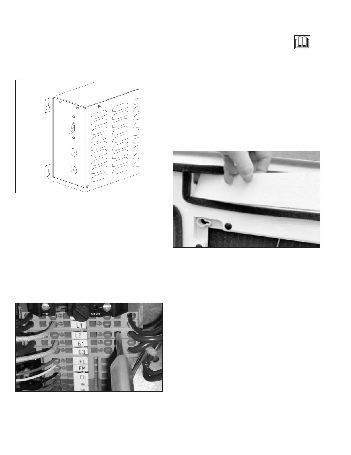
Disconnect Switch
For models with a factory installed disconnect switch (Digit 12 =
D), the switch will be installed on the side of the control panel.
See Figure 20.1, Figure 21.1, Figure 22.1, Figure 23.1 and
Figure 24.1 for the location of the control panel on the unit.
Figure 12.1 - Factory Installed Disconnect Switch
Terminal Strip Connections
The terminal strip connections are designed to clamp down on
the wires. To properly connect the wires to the terminal strip:
1. Push a small at head screwdriver into the square hole on
the terminal. Press rmly until the screwdriver hits the back
stop and opens the terminal. See Figure 12.2.
2. Remove approximately 3/8 in (9.5 mm) of insulation from
the end of the wire and push the stripped wire into the oval
hole in the terminal.
3. Remove the screwdriver. Pull on the wire to make sure that
it is securely clamped in the terminal.
4. Make sure that the terminal clamp is in contact with bare
wire (insulation removed).
Figure 12.2 - Terminal Strip
Remote Condensing Unit Terminal Strip
Connections
Connect remote condensing unit thermostat wires into the
appropriate terminal strip connections. These connections
are Safety Extra-Low Voltage (SELV) and are indicated on the
wiring diagram by the "read the instructions" symbol
See wiring diagram for specics.
Fascia Assembly
1. Once the services have been connected, the four (4) fascia
mounting bolts can be unscrewed approximately 1 in (2.54
cm) from the condensate tray support channels.
2. The fascia can now be unpacked for tting to the unit
chassis. Ensure the black r tree fasteners holding the
fascia polystyrene are pushed in rmly in case of transit
vibration.
3. If a fascia aperture needs blanking o, then take one of the
polystyrene blanking pieces and push it into the recess in
the polystyrene fascia insulation. See Figure 12.3.
Note: Up to two non-adjacent sides can be blanked o.
Figure 12.3 - Fascia Blanking Piece
Note: Make sure the foam insulating strip prole on the fascia
matches the square and angled corners of the unit
housing.
4. Install the fascia by removing the inlet grilles and lters,
locating the four fascia mounting bolts on the chassis
through the four keyhole brackets on the fascia and then
sliding the fascia sideways until it locks into position.
5. Before tightening the fascia to the unit, connect the two
halves of the vane motor’s plug and socket connection
(medium and large size units – Model Digit 4,5 = 18 and
higher).
6. On microprocessor controlled units (Model Digit 8=M),
ensure that the display panel cable is routed to the
electrical panel and securely fastened to its connector
on the microprocessor circuit board. Refer to the unit’s
electrical wiring schematic. Take care to ensure that the
connector is connected in the proper orientation and
that the wires are not routed such that they may become
trapped, cut, broken or chafed.
7. The fascia can now be tightened up to the unit chassis until
a good seal is obtained between fascia and chassis.
Note: Do not over tighten the bolts. To do so may cause
damage to the fascia.
8. With lters in place, the inlet grilles can now be tted to the
fascia to complete the installation.