8
8-504.11
INSTALLATION
Installation
IMPORTANT
For ceiling mounted units, check that the ceiling is capable of
supporting the weight of the unit. If used within a ceiling grid,
the ceiling grid is to be supported separately from the unit.
IMPORTANT
Pour les unités installées au plafond, vériez que le plafond
peut soutenir le poids de l’unité. En cas d’utilisation au
sein d’un support de plafond, ce dernier doit être soutenu
séparément de l’unité.
Hanger Bolts
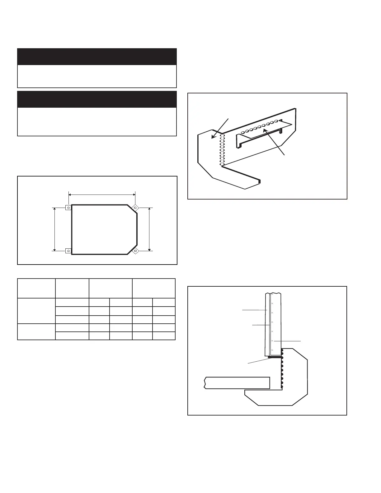
The hanger bolts can now be installed (use 3/8” all thread rod)
at the centers shown in Figure 8.1 and Figure 8.2.
Figure 8.1 - Hanger Bolt Mounting Dimensions
A
Table 8.1 - Hanger Bolt Mounting Dimensions
Unit
Conguration
(Digits 2,3)
Nominal
Capacity
(Digits 4,5) A B
CW
08, 12 19.5 in 49.5 cm 23.0 in 58.4 cm
18, 20 28.5 in 72.4 cm 31.5 in 80.0 cm
33, 36 28.5 in 72.4 cm 43.5 in 110.5 cm
SD/SH
18, 24 28.5 in 72.4 cm 31.5 in 80.0 cm
30, 36, 42 28.5 in 72.4 cm 43.5 in 110.5 cm
Refer to the manufacturer’s hanger bolts technical sheet to check the strength of
the unit mounting hanger bolts. Ensure the bolts can hold the weight of the unit.
Refer to Table 26.1, Table 27.1,Table 28.1 andTable 29.1 for unit weights.
Installation Guide
An installation guide is included in the Owner Information packet
provided with the unit. The installation guide sets the proper
height between the chassis and ceiling. Prepare the installation
guide by folding the at metal piece, by hand, along the
perforations as shown in Figure 8.2.
Figure 8.2 - Installation Guide Setup
FOLD TAB UP
FOLD SIDE BACK
Use an adequate number of personnel when moving the unit.
A lifting device or at least two personnel should be used to
lift the unit. The unit can be lifted onto the hanging rods and
leveled at the correct distance from the ceiling with the aid of the
installation guide.
1. Hold the tab on the installation guide against the bottom
of the cassette case with the guide pointing away from the
cassette. See Figure 8.3.
2. Adjust the height of the cassette until the guide is level with
the bottom of the false ceiling.
Figure 8.3 - Installation Guide Position
OUTER CASE
INSULATION
FALSE CEILING
GUIDE IN POSITION
CASSETTE CASE
INNER CASE
INSULATION
TAB
3. Secure the unit in position with locknuts and washers
on both sides of the unit bracket. It is recommended to
have two 3/8” locknuts and washers on the bottom of the
threaded rod. Ensure the threaded rod does not protrude
more than 2 in (5 cm) below the mounting bracket as
shown in Figure 9.1.