18
8-504.11
MICRO-PROCESSOR OPERATION
Micro-Processor Controls Operation
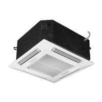
Receiver
The IR receiver is an extension of the control board and is
located on the fascia of the unit, connected by means of a 7-pin
plug and socket.
Figure 18.1 - Unit Mounted Receiver
The microprocessor controller has a built-in diagnostics feature
so that in the event of an alarm, the nature of the fault can be
determined. The yellow timer/alarm LED ashes on the fascia in
a pre-determined frequency depending on the fault. These are
identied below in Table 18.1.
Table 18.1 - LED Identication
LED NAME LED State System State
"On" ON ON
"On" OFF OFF
"Timer" Blinking a. Timer ON
b. Power returned after break
while Timer was active
"Timer" & "On" Blinking synchronous a. Fault "F1" indication – error
with unit mounted return air
sensor.
b. Fault on T4,0 input (input
was opened more than 10
seconds)
- Condensate High Level
- Freeze stat alarm
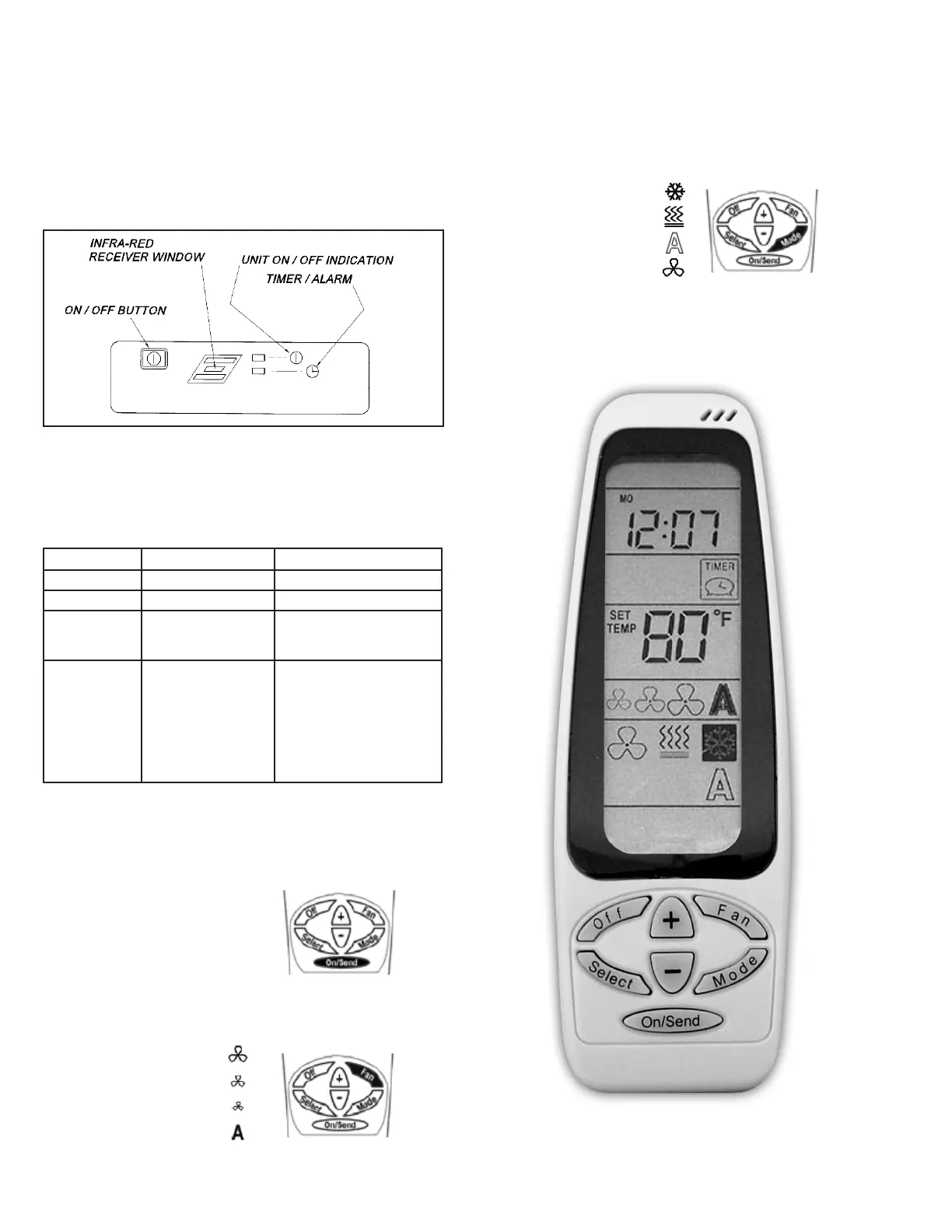
Transmitter
On/O
Press the ON/SEND button to activate the cassette unit and/or
updating information.
Fan Speeds
Press the FAN button to switch between fan speeds:
High Speed
Medium Speed
Low Speed
Auto Speed
Press the ON/SEND button to send information to the cassette
unit.
Modes
Press the MODE button to switch between:
Cool
Heat
Auto Change-over
Fan Only
Press the ON/SEND button to send information to the cassette
unit.
Figure 18.2 - Remote Transmitter