9
8-504.11
INSTALLATION
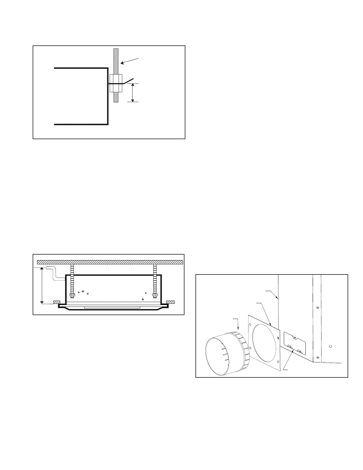
Figure 9.1 - Threaded Rod Dimension
Threaded Rod
< 2 in (5 cm)
3/8 in
Condensate Piping
The unit is supplied with a 3/8" ID exible hose for connection to
copper or plastic drain piping.
When installing the unit consider the following:
1. Maximum pump lift is 30 in (76.2 cm).
2. The highest point in the condensate piping should be as
close to the unit as possible.
3. Condensate piping should slope downwards in the direction
of water ow with a minimum gradient of 1 in per 100 in
(2.54 cm per 254 cm). There must not be any upward
gradients other than in the rst 30 in (76.2 cm) of piping
from the unit. Once the piping begins the downward
gradient, the piping must continue to be in a downward
gradient. See Figure 9.2.
Figure 9.2 - Condensate Piping
30 in
(76.2 cm)
Max
4. When multiple units are connected to a common
condensate drain, ensure the drain is large enough to
contain the volume of condensate from all units. It is
recommended to have an air vent in the condensate piping
to prevent any air locks.
5. Condensate piping must not be installed where it may be
exposed to freezing temperatures.
Duct Collars
Supply air branch duct and outside air duct collars can be
attached to the unit chassis by following the below steps:
Supply Air Duct Collars:
1. Up to two supply air ducts can be attached per unit.
2. Place the polystyrene blanking strip in the fascia supply air
opening on the same side where the supply duct collar is to
be installed.
Outside Air Duct Collars:
1. Two outside air openings are available on small casing
sizes (size 08 & 12). Three outside air openings are
available on medium and large casing sizes (size 18 and
higher).
2. Replace the washable lter with the pleated lter provided
with the fresh air duct collar kit.
3. To maximize the amount of outside air through the
knockouts, use all available fresh air openings, the pleated
lter, and high fan speed.
Installing Outside and/or Supply Air Duct Collars:
1. Refer to the dimensional drawing on page 20 page 24
to for knock-out hole locations.
2. The insulation is pre-cut to aid location and removal of the
relevant section. Rub hand across surface of insulation to
reveal exact location of knock-out.
3. Remove the metal knockout from the chassis.
4. Place the duct collar’s tabs inside the duct collar ange’s
opening. Bend the tabs around the duct collar ange’s
opening.
5. Using eld provided self-tapping screws, attach the duct
ange and collar to the chassis with the bent tabs being
sealed in between the unit chassis and duct collar ange.
See Figure 9.3 for duct collar assembly.
Figure 9.3 - Duct Collar Assembly
DUCT COLLAR
DUCT COLLAR FLANGE
UNIT CHASSIS
OUTSIDE AIR KNOCKOUT
Note: See Figure 20.1, Figure 21.1, Figure 22.1, Figure 23.1
and Figure 24.1 for Branch Duct and Fresh Air Duct
locations and dimensions.