EasyManua.ls Logo

Moduline CVE031E - INSTRUCTIONS for WATER CONNECTION (if Available)

Moduline CVE031E
69 pages
Print Icon
To Next Page IconTo Next Page
To Previous Page IconTo Previous Page
Loading...
USA Ed. 0215
2 • INSTALLATION INSTRUCTIONS
INSTALLATION
Water connection
At the back of the machine, there are 2 inputs for hydraulic connection with ¾ male thread. They are indi-

 
 





connection pipes that have already been used.
Softened water input






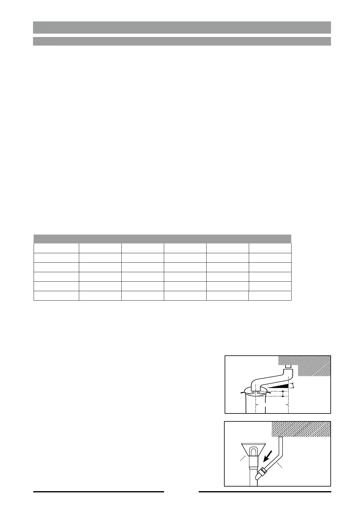
WATER HARDNESS PARAMETER CONVERSION TABLE
1 °fH (°tH) °dH °eH (Clark°) ppm (mg/lt) gr/gal (US)
1 °fH (°tH) 1 0,56 0,7 10 0,6
1 °dH 1,79 1 1,25 17,9 1,07
1 °eH (Clark°) 1,43 0,8 1 14,28 0,86
1 ppm (mg/lt) 0,1 0,06 0,07 1 0,06
1 gr/gal (US) 1,71 0,96 1,2 17,15 1
Mains water input
Used for the cooling of the oven discharge.
Discharge





channelled into a continuous system, while a gap of at least 25mm

WARNING! – The drain line, as shown in the drawing,





2.4 - INSTRUCTIONS FOR WATER CONNECTION (IF AVAILABLE)
Max. 200 cm
Min. 4
25 mm.
Hose
Vent
opening

Table of Contents

Related product manuals