Installation
74
05/01 AWB2700-1384GB
Wiring
The figure below shows the minimum wiring with shielding
between two bus subscribers using D-type connectors. The column
containing 3, 5, 6 and 8 shows the pin assignment when the next
bus station is to be connected via D-Type connector, e.g.
WIN
bloc
DP modules, repeater, etc.
Figure 28: Minimum wiring between two connections
* VP = Supply voltage (+) for external bus termination
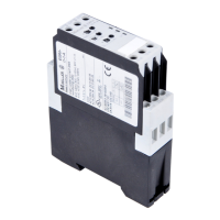
Figure 29: Bus connection
Module 1 Module 2
RxD/TxD-P B' 3 B 3 RxD/TxD-P
DGND GND 5 GND 5 DGND
VP* +5 V 6 +5 V 6 VP
RxD/TxD-N A' 8 A 8 RxD/TxD-N
Protective
Ground
Protective
Ground
h
Both signal wires must never be cross connected!
Shield
 Loading...