-21-
Revision 2/F3509
Correct coil resistance: 3650 ohms
NOTE: If open circuit / high resistance, then
the coil is faulty—replace.
If coil resistance is correct, rewire and listen
for an audible solenoid click when the steam
switch is depressed.
If solenoid can be heard functioning, and oven
water nozzle is not blocked, then remove
water solenoid and fittings and check for
blockages.
6.1.6 CONTINUOUS WATER OUT OF OVEN
WATER NOZZLE
Water solenoid electrical fault
With control panel steam switch not
depressed, check for power supply across
solenoid coil. If there is power to the coil, then
check wiring and steam switch (refer 6.1.5).
6.1.7 60 MINUTE TIMER NO TIME UP
BUZZER
Buzzer faulty
With timer in ‘zero’ position, check the buzzer
at side of control panel (inside) for voltage
across terminals. If voltage is correct then
buzzer is faulty—replace.
If there is no voltage, then check wiring.
Timer not switching on buzzer
With timer in zero position, check voltage to
top connection (terminal one) and bottom
connection (terminal two) of timer. If there is
no voltage at terminal one then check wiring.
If no voltage at terminal two then timer is
faulty—replace.
NOTE: Timer will continue to run
approximately three minutes below zero.
Buzzer and time up indicator will continue until
the timer is manually switched off (to vertical
position).
6.1.9 NO HEAT
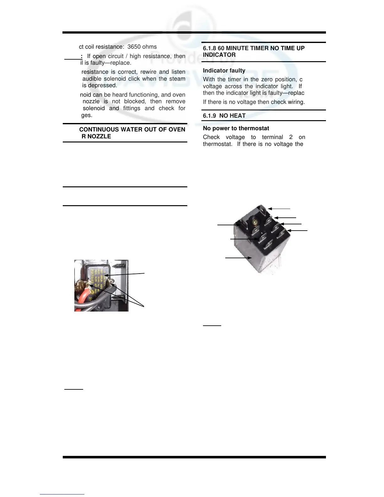
No power to thermostat
Check voltage to terminal 2 on oven
thermostat. If there is no voltage then check
voltage through terminal 5 and one on hold
relay (behind control panel). If there is no
voltage to terminal 5 then check wiring. If
there is no voltage to terminal 1 then check
that the hold relay has no power at relay coil
terminal 7. If relay coil is not energised (ie no
power at 7) and no power out of terminal 1,
then the relay is faulty—replace.
6.1.8 60 MINUTE TIMER NO TIME UP
INDICATOR
Indicator faulty
With the timer in the zero position, check for
voltage across the indicator light. If correct,
then the indicator light is faulty—replace.
If there is no voltage then check wiring.
Thermostat faulty
Set thermostat to 200°C or 400°F. Check the
voltage out of terminal 1 on the thermostat. If
there is no voltage then the thermostat is
faulty—replace.
If the voltage is correct and the heating light is
on then check all wiring to heating contactor.
Heating contactor faulty
With thermostat on, check that the heating
contactor coil has power to terminal A1 and
voltage across the coil, terminals A1 and A2.
If incorrect check wiring.
If voltage is correct, check that contactor pulls
in and closes the contacts when power to con-
Buzzer
Buzzer Terminals
Figure 6.1.2
If relay is energised (ie power at 7) then
’Roast n Hold’ switch is on and unit is in hold
mode. Turn off ’Roast n Hold’ and recheck
operation.
NOTE: There should be no voltage across
these terminals when ‘Roast ‘n Hold’ is not
selected.
Figure 6.1.3
7
5
3
1
8
4
Relay