-28-
Revision 2/F3509
6.3.12 WATER SOLENOID
6.3.15 ELEMENTS
6.3.14 SPRAY NOZZLE
1) Ensure water supply is turned off.
2) To access the solenoid, remove the rear
access panel (refer 6.2.3)
3) To remove or replace solenoid, discon-
nect water solenoid from oven water tube
behind water solenoid with a 1/2” (13mm)
spanner.
4) Remove water solenoid from oven by
removing two screws securing the water
solenoid bracket to electrical supply
junction box.
5) Carefully withdraw solenoid (including
wires and bracket).
5) Replace or service solenoid as required.
6) To reinstall, reverse procedure.
7) Check water connections do not leak.
8) Check for correct water injection opera-
tion.
Figure 6.3.18
1) Inside the oven remove the RH side fan
baffle, then unscrew the spray nozzle.
1) Remove service panel (refer 6.2.2) and
baffle.
2) Rremove the wires from the elements.
Figure 6.3.19
Spray Nozzle
2) Clean or replace as required, ensuring
debris free on re-assembly.
3) Ensure that the spray nozzle is installed in
the vertical position.
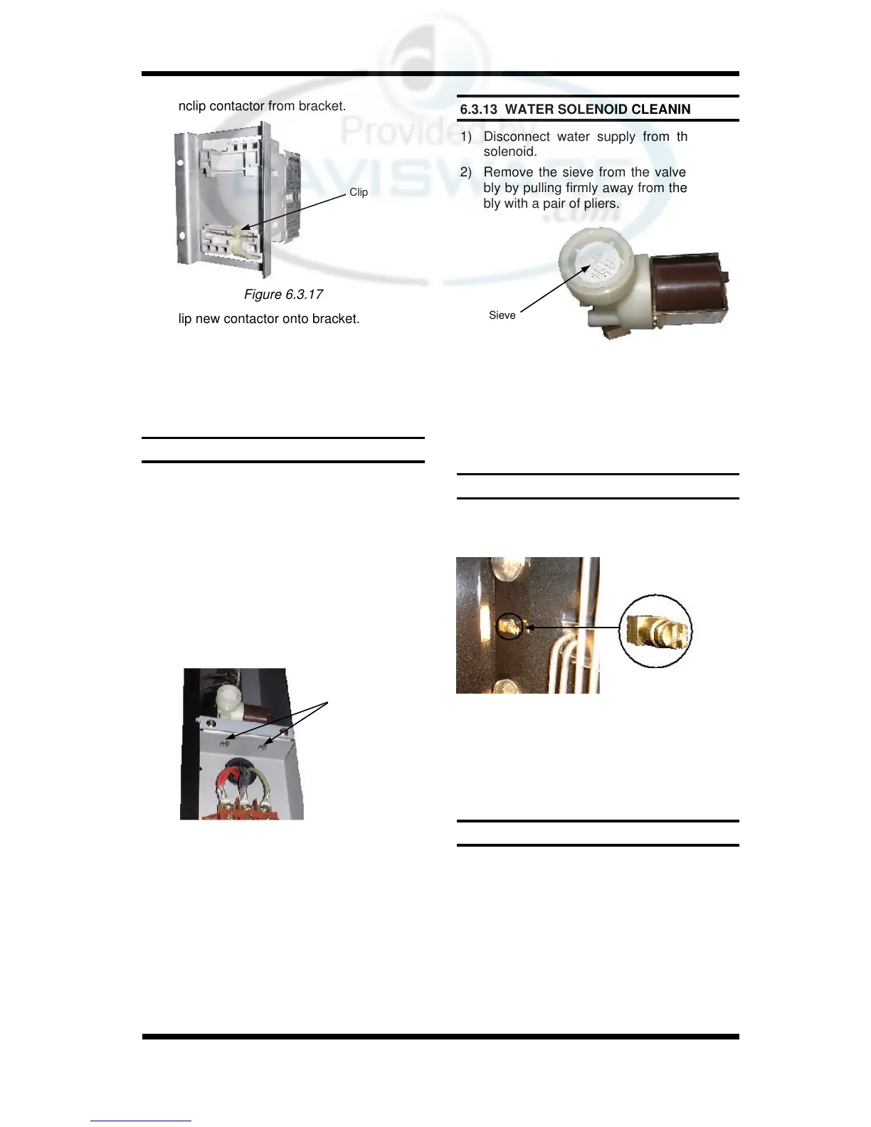
6.3.13 WATER SOLENOID CLEANING
1) Disconnect water supply from the water
solenoid.
2) Remove the sieve from the valve assem-
bly by pulling firmly away from the assem-
bly with a pair of pliers.
Sieve
4) Clean the sieve, removing all dirt and
grime.
5) Replace the sieve and reconnect the wa-
ter supply.
Figure 6.3.20
Two Screws
2) Unclip contactor from bracket.
Figure 6.3.17
Clip
3) Clip new contactor onto bracket.
4) Secure new heating contactor and bracket
to oven with two screws.
5) Transfer wires from old contactor to new
contactor, ensuring all wires are in their
correct positions.