-25-
Revision 2/F3509
Two Screws
6.3 REPLACEMENT
6.3.1 LIGHT BULB / GLASS
6.3.2 DOOR MICROSWITCH
1) Unscrew lamp cover(s).
1) Hinge down control panel (refer 6.2.1)
2) Remove two screws holding microswitch
to bracket.
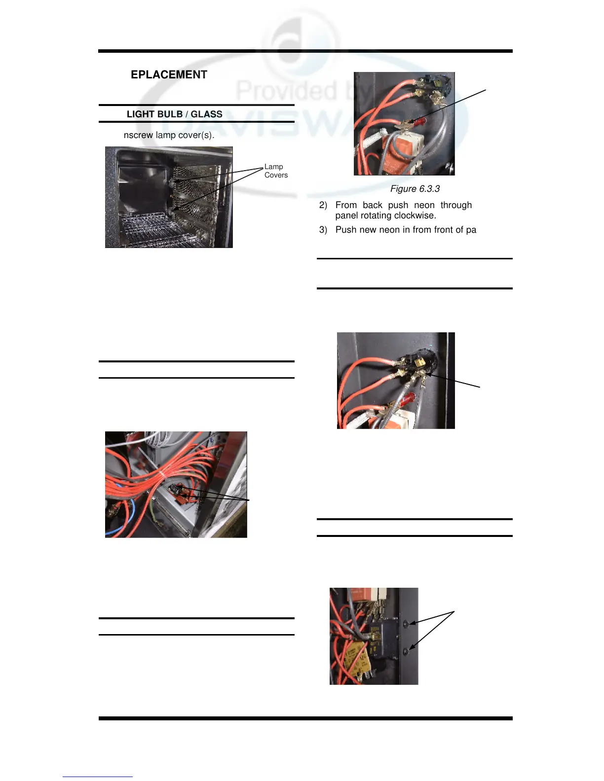
6.3.3 INDICATOR NEON LIGHT
1) With control panel open (refer 6.2.1) re-
move the wires from the back of the neon.
6.3.4 POWER / ROAST / LIGHTS / STEAM
SWITCHES
1) With control panel open (refer 6.2.1) re-
move the wires from the back of the
switch, noting their positions.
Two Screws
6.3.5 BUZZER
1) Remove control panel (refer 6.2.1).
2) Remove two screws holding buzzer
bracket to panel.
Figure 6.3.5
2) Unscrew bulb out of fitting.
3) Screw in replacement bulb.
4) Ensure seal fitted. Screw lamp cover into
holder with baffle fitted (do not over
tighten).
Lamp
Covers
Figure 6.3.1
3) Transfer wires to new switch and re-
assemble.
4) Adjust micro-switch (refer 6.4.2).
Figure 6.3.2
2) From back push neon through front of
panel rotating clockwise.
3) Push new neon in from front of panel, and
reconnect wires.
2) From back push switch through front of
panel.
3) Push new switch in from front of panel,
and reconnect wires.
Neon
Wires
Switch
Wires
Figure 6.3.3
Figure 6.3.4