-7-
Revision 2/F3509
Refer to specifications section for minimum
wire connections required.
WATER CONNECTION
A cold water supply should be fitted to the
water inlet (3/4” BSP hose connection) which
is located on the rear of the right hand side of
the unit.
Alternately, a connection elbow and sealing
washer is supplied with this unit for direct
connection of a 1/2” ID hose, and is
recommended for easy installation and ser-
vice.
Connect water supply - Max inlet pressure
80psi / 550kPa.
Turn on water supply to check for leaks.
It is most important that the oven is installed
correctly and that the operation is correct be-
fore use. Installation shall comply with local
electrical, health and safety requirements.
BEFORE CONNECTION TO POWER
SUPPLY
Unpack and check unit for damage and report
any damage to the carrier and dealer. Report
any deficiencies to your dealer. Fit the feet
which are packed inside the oven. Fit door
handle to oven door. Check that the available
power supply is correct to that shown on the
rating plate located on the right-hand side
panel.
208 V AC 60 Hz, 28.8 A , 6.0 kW@ 208 V
220-240 V AC 60 Hz, 27.8 A, 6.7 kW @ 240 V
208-220 V AC 50 Hz, 28.8 A, 6.0 kW @ 208 V
230-240 V AC 50 Hz, 27.8 A, 6.7 kW @ 240 V
LOCATION
To ensure correct ventilation for the motor and
controls the following minimum installation
clearances are to be adhered to:
Rear 40mm / 1.5“
Left-hand side 40mm / 1.5”
Right-hand side 40mm / 1.5”
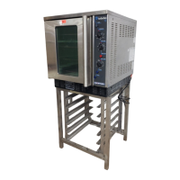
Position the oven in its allocated working
position. Use a spirit level to ensure the oven
is level from side to side and front to back. (If
this is not carried out, uneven cooking could
occur). The feet/legs used with bench or floor
mounting or provided with stands are adjust-
able and will require adjusting in levelling the
unit. It should be positioned so the operating
panel and oven shelves are easily reachable
for loading and unloading.
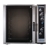
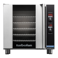
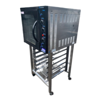
2. INSTALLATION
IMPORTANT: THE OVEN VENT
LOCATED ON THE CABINET TOP
MUST NEVER BE OBSTRUCTED.
WARNING: THIS APPLIANCE MUST BE GROUNDED.
BEFORE USE
Operate the oven for about 1 hour at 200°C
(400°F) to remove any fumes or odours which
may be present.
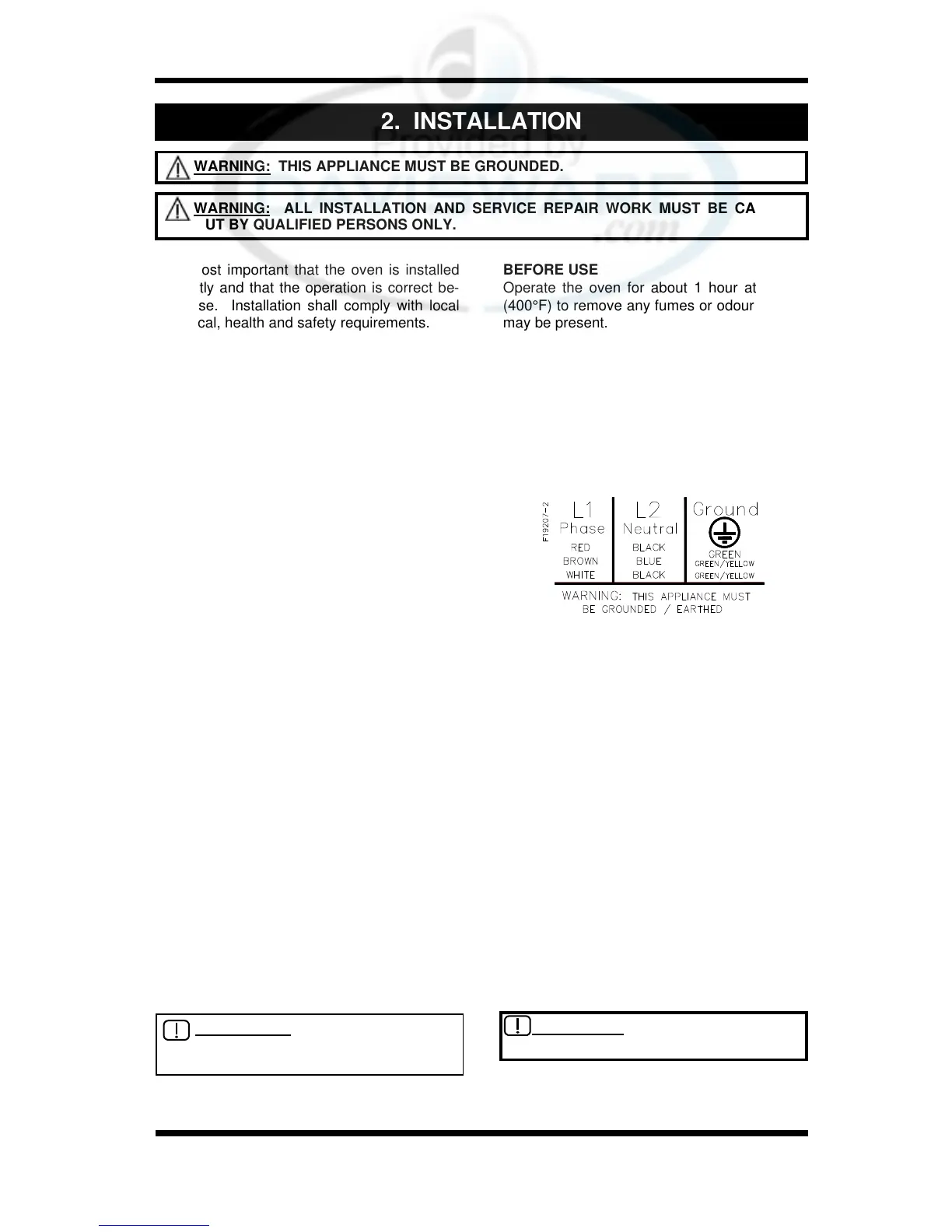
ELECTRICAL CONNECTION
Remove rear cover panel to allow access to
the terminal block and strain relief cable
clamp. The cable can be fitted through the
small grommet and held by the cable clamp.
Connect cable to the terminals as marked.
Refit cover panel.
Figure 2.1
IMPORTANT: MAXIMUM INLET WATER
PRESSURE IS 550 kPa / 80 psi.
WARNING: ALL INSTALLATION AND SERVICE REPAIR WORK MUST BE CARRIED
OUT BY QUALIFIED PERSONS ONLY.