– 18 –
∗
∗∗
∗80 OUTPUT FUNCTION MENU MODE
(press
∗
∗∗
∗
80 while in Programming mode)
The Output Definition Worksheet is on page 30.
Use this mode to program output function definitions (up to 48 functions) that provide automated control of any of the output
devices, based on events occurring on individual zones or zones with certain zone types.
Each output definition is identified
by an output function number, and includes the following components:
Output Definition Components
Component Description
Output Function No. A reference number that defines an output’s characteristics.
Activated By Determines whether the initiating event occurs on a zone, a zone list, or a zone type.
Event Event that triggers the output action. Can be an event occurring on a specific zone number or a
zone list, or a specific zone type.
Partition If the output is activated by zone type, this defines the partition in which the programmed event is
to cause the device action.
Output Action Defines the action of the relay/X-10 device when the defined event occurs. Can close for 2
seconds, stay closed until reset, continuously pulse (1-second close-open-close-open, etc.),
toggle the device state, or activate for a defined duration (set in data field *177).
Output No. Assigns this function to a specific output number (defined in *79 Menu Mode). This is the output
number that will perform this function upon the triggering event. Note that each defined function is
associated with only one output number. This means that if more than one output device needs to
perform this particular function, you need to define another output function number with the same
attributes, but assign the appropriate output number. (i.e. output devices can be assigned more
than one function number, but each function number can only be assigned a single output
number.
For example, if you want to pulse a strobe light upon fire alarms on zone 4 using a relay mapped to output number 2 (as
programmed in *79 Menu Mode), program the following in *80 Menu Mode:
Prompt Entry
Output Funct. # = 01 (assuming this is the first output function)
Activated By: = 3 (zone number)
Enter Zn No. = 04 (requires 2-digit zone numbers)
Output Action = 3 (continuous pulse)
Output Number = 02 (device mapped in *79 Menu Mode)
OUTPUT FUNCT. #
Enter the output function number to be defined
(VISTA-20PMT: 01-48; VISTA-15PMT: 01-24).
[∗] to continue; 00 = exit
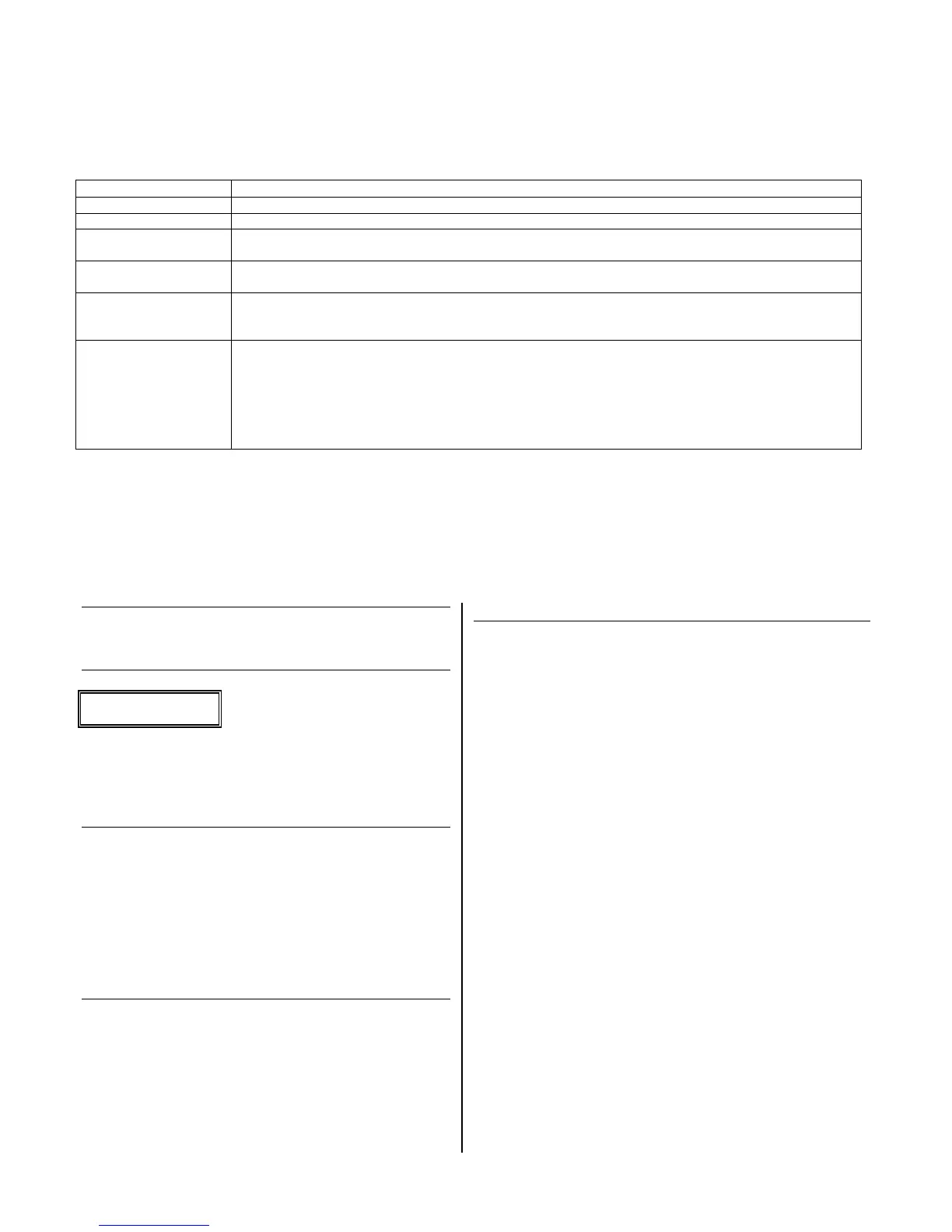
SUMMARY SCREEN
01 A E P Trig
?00 0 0 – ZL=00
This screen displays a summary of the current output
programming
A = Output Action; E = Triggering event; P = Partition;
Trig = Trigger type
Question mark indicates the device shown has not been mapped.
Use *79 Menu mode to map the device.
[∗] to continue
ACTIVATED BY
0 = delete (deletes the output function and any previous
programming); a confirmation prompt appears.
To delete this output definition, press 1. If you do not want to
delete this output, press 0.
1 = zone list (go to “A” prompt); 2 = zone type (go to “B” prompt);
3 = zone number (go to “C” prompt)
Press [∗] to continue
Select where the initiating event for this output definition is to
occur
“A” (if zone list was selected)
ZN LIST
Enter the desired zone list number (01-08). At the ENTER
EVENT prompt, enter the zone list event that will activate this
output (0 = restore; 1 = alarm; 2 = fault; 3= trouble)
Press [∗] to continue and skip to the “Output Action” prompt.
NOTE: For alarm, fault, and trouble, an event on ANY zone in the
list activates the output, but ALL zones in the list must be
restored before the output is restored.
“B” (if zone type was selected)
ENTER ZN TYPE
Enter the desired zone type. See list below *80 Worksheet for zone
types.
At the PARTITION prompt, enter the partition in which this zone type
will occur (0 = any partition; 1 = part 1; 2 = part 2; 3 = part 3).
Press [∗] to continue and skip to the “Output Action” prompt.
CHOICES FOR ZONE TYPES:
00 = Not Used 05 = Day/Night 14 = Carbon Monoxide††
01 = Ent/Exit #1 06 = 24 Hr Silent 15 = Medical
02 = Ent/Exit #2 07 = 24 Hr Audible 16 = Fire w/verification
03 = Perimeter 08 = 24 Hr Aux 23 = No Alarm Response
04 = Interior Follower 09 = Fire 24 = Silent Burglary
10 = Interior w/Delay 77 = Keyswitch Zone
12 = Monitor Zone 81 = AAV Monitor Zone
90-91 = Configurable
CHOICES FOR SYSTEM OPERATION:
20 = Arming–Stay 36 = **At Bell Timeout*** 58 = Duress
21 = Arming–Away 38 = Chime 60 = AAV
22 = Disarming 39 = Any Fire Alarm 61 = AVS/GSMV
session begin §
31 = End of Exit Time 40 = Bypassing 62 = AVS/GSMV
session end §
32 = Start of Entry Time 41 = **AC Power Failure 66 = Function Key†
33 = Any Burglary Alarm 42 = **System Battery Low 67 = Bell Fail
43 = Comm. Failure 68 = Telco Line Cut
52 = Kissoff 78 = Keyswitch Red LED
54 = Fire Zone Reset 79 = Keyswitch Green LED
** Use 0 (Any) for Partition No. (P) entry.
*** Or at Disarming, whichever occurs earlier.
† Use *57 Menu Mode to assign the function key (function “07”).
†† when used with an output function, the carbon monoxide zone type
activates upon CO alarms only. Does not activate for trouble
conditions.
§ automatically set when appropriate AVS Quick Command
performed.
Note: In normal operation mode:
Code + # + 7 + NN Key Entry starts Device NN.
Code + # + 8 + NN Key Entry stops Device NN.
 Loading...