– 4 –
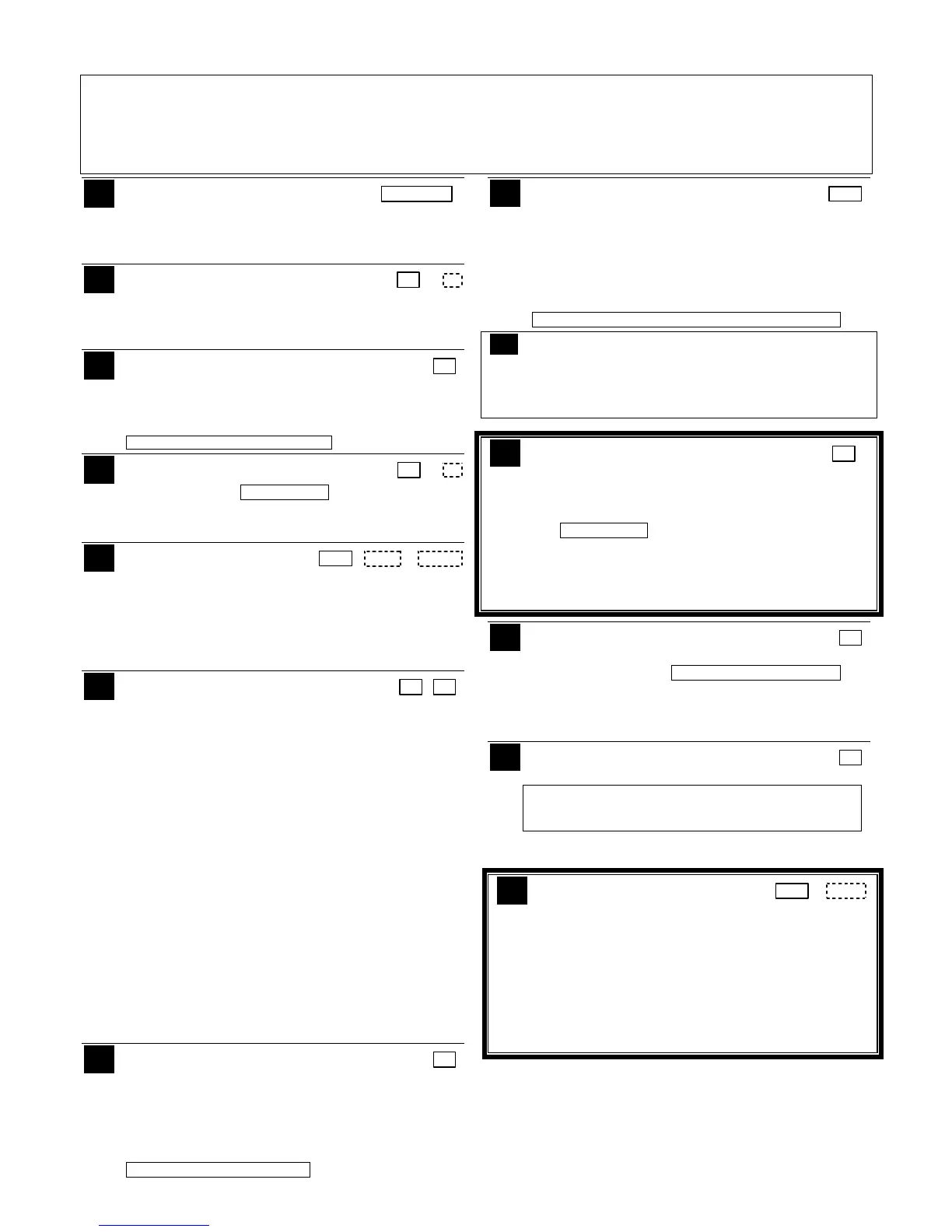
DATA FIELD PROGRAMMING FORM
Entries apply to both the VISTA-15PMT and VISTA-20PMT controls, except entries
shown in dashed boxes apply only to the
VISTA-20PMT (partition entries) and are not applicable to the VISTA-15PMT.
Entry of a number other than one specified will give unpredictable results. Values shown in brackets are factory defaults.
SIA Features:
The VISTA-15PMT and VISTA-20PMT are certified SIA-compliant controls that meet SIA specifications for
False Alarm Reduction. Fields marked with heavy borders are related to SIA requirements and have entries or operation
different than non SIA-compliant controls.
∗
∗∗
∗20 Dealer Installer Code
[4112] | | |
4 digits, 0000–9999 This code can perform all system
functions except cannot edit the central station reporting
phone numbers (fields *41, *42). For security purposes, the
factory default installer code should be changed.
∗
∗∗
∗21 Quick Arm Enable
[1,1]
0 = no; 1 = yes Part. 1 Part.2
If enabled, users can press the [#] followed by an arming
key to arm the system instead of using a security code. The
security code is always needed to disarm the system.
∗
∗∗
∗22 RF Jam Option
[0]
0 = no RF Jam detection
1 = send RF Jam report
If enabled, a report is sent if the system detects an RF
jamming signal.
UL: must be 1 if wireless devices are used
∗
∗∗
∗23 Quick (Forced) Bypass
[0,0]
0 = no quick bypass
UL: must be “0” Part. 1 Part. 2
1 = allow quick bypass (code + [6] + [#] )
Zones bypassed by this function will be displayed after the
bypass is initiated.
∗
∗∗
∗24 RF House ID Code
[00,00,00]
| | |
00 = disable wireless keypads Part. 1 Part. 2 Common
01–31 = using 5827, 5827BD or 5804BD keypad
The House ID identifies receivers and wireless keypads. If a
5827 or 5827BD Wireless Keypad or 5804BD Transmitter is
being used, a House ID code must be entered and the
keypad set to the same House ID. You can assign RF house
ID for each partition
∗
∗∗
∗26 Chime By Zone
[6, 7]
KP (Keypad) Sound Enables 1 2
Entry 1
0 = no “entry 1” keypad trouble sounds, AND no chime by
zone (keypad chimes on fault of any entry/exit or
perimeter zone when chime mode is on)
1 = Chime by Zone enabled (l
ist chime zones on zone
list 3 using *81 Menu mode)
2 = Communication device (LRR) Trouble sounding
enabled (for communication devices such as
7845GSM, 7845i-GSM, GSMV)
4 = System Low Battery sounding enabled
7 = select all entry 1 options
Entry 2
0 = no “entry 2” keypad trouble sounds
1 = RF Supervision sounding enabled
2 = RF Low Battery sounding enabled
4 = RF Jam sounding enabled
7 = select all entry 2 options
For each entry, enter the sum of the desired options.
Example Entry 1: for Chime by Zone and System Low
Battery sounding, enter 5. To enable all options, enter 7.
Keypad (KP) Trouble Sounding can be enabled/disabled for
the conditions listed in each entry.
∗
∗∗
∗27
Powerline Carrier Device (X–10)
[0]
House Code
0 = A; 1 = B; 2 = C; 3 = D; 4 = E; 5 = F; 6 = G; 7 = H; 8 = I;
9 = J; #10 = K; #11 = L; #12 = M; #13 = N; #14 = O; #15 = P
Powerline Carrier devices require a House ID, identified in
this field. Program Powerline Carrier devices in interactive
modes ∗79, *80 and *81.
UL: not for fire or UL installations
∗
∗∗
∗28 Access Code for Phone Module [00]
|
00 = disable;
(Partition 1 only)
1st digit: enter 1–9; 2nd digit: enter # + 11 for "
✱
", or # + 12
for "#".
You must assign a 2-digit access code for the 4286 Phone
Module, if used. Example: If desired access code is 7∗, then
7 is the first entry, and [#] + 11 (for ∗) is the second entry.
NOTE: A 0 in either digit disables the phone module.
UL: must be “00” for UL Commercial Burg. installations
∗
∗∗
∗29 Enable IP/GSM – Communication Device Menu
Mode (pass-through programming)
This is a Menu Mode command, not a data field, for programming
IP/GSM communication device options. See ∗29 Menu Mode
section later in this document.
∗
∗∗
∗31 Single Alarm Sounding Per Zone
[0]
0 = “alarm sounding per zone” will be the same as the
“number of reports in armed period” set in field *93 (1 if
one report, 2 if 2 reports, unlimited for zones in zone list
7)
UL: must be “0”
SIA: Must be “0” if *93 Reports in Armed Period is set
to “2” report pairs.
1 = one alarm sounding per zone
If enabled, limits alarm sounding on the bell output to once
per zone per armed period.
∗
∗∗
∗32 Fire Alarm Sounder Timeout
[0]
0 = sounder stops at timeout;
1 = no sounder timeout UL: must be “1” for fire install.
This control complies with NFPA requirements for temporal
pulse sounding of fire notification appliances. Temporal
pulse sounding for a fire alarm consists of the following: 3
pulses – pause – 3 pulses – pause – 3 pulses.
∗
∗∗
∗33 Alarm Sounder (Bell) Timeout
[1]
0 = none; 1 = 4 min; 2 = 8 min; 3 =12 min; 4 = 16 min;
UL: For residential fire alarm installation, must be set for
a minimum of 4 min (option 1); for UL Commercial
Burglary installations, must be minimum 16 min (option 4)
This field determines whether the external sounder will shut
off after time allotted, or continue until manually turned off.
∗
∗∗
∗34 Exit Delay
[60,60]
| |
45 - 96 = 45 - 96 secs; 97 = 120 secs Part. 1 Part. 2
NOTE: Entries less than 45 will result in a 45-second delay.
UL installations: For UL Commercial Burglar Alarm and UL
Residential Burglar Alarm installations with line security,
total exit time must not exceed 60 seconds.
Common zones use part. 1 delay.
The system waits the time entered before arming entry/exit
zones. If the entry/exit door is left open after this time
expires, an alarm will occur. Common zones use same
delay as partition 1.