HLN6923A October 12, 2005
Standard Configurations: Planning the Installation 2-3
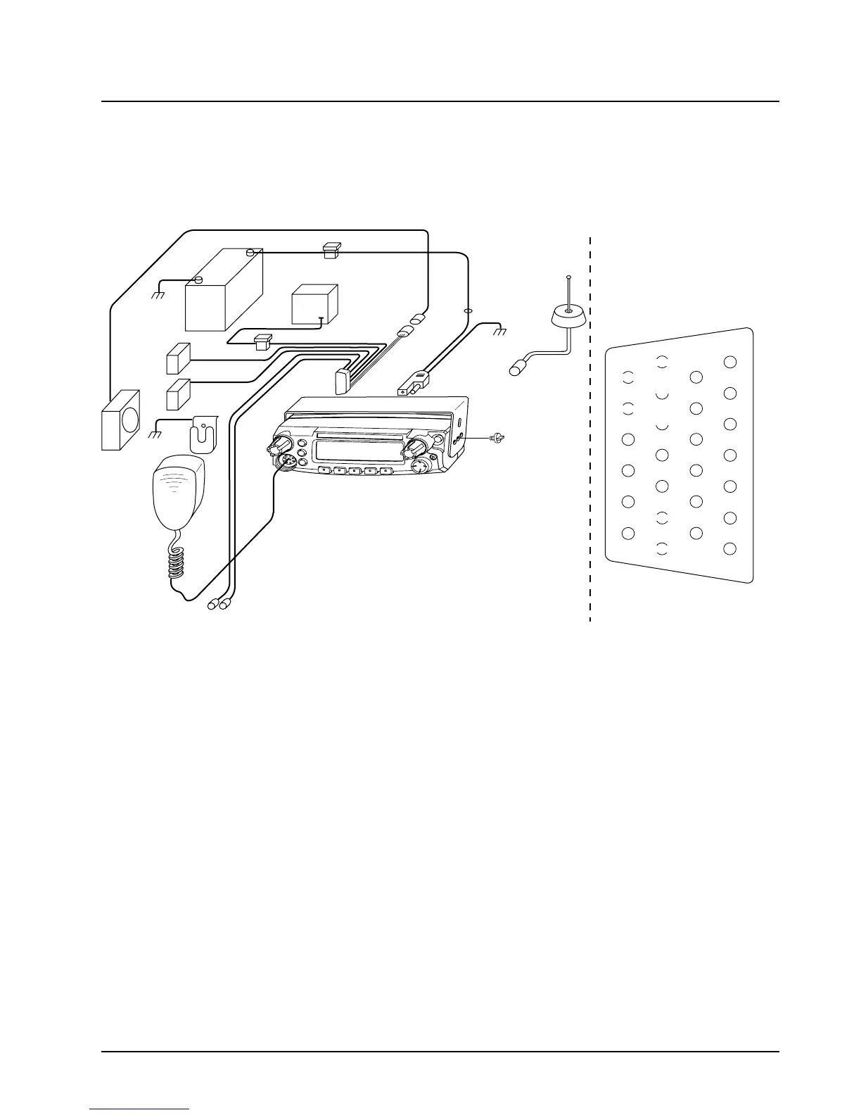
2.1.2 Wiring Diagrams
Figure 2-7 through Figure 2-9 show the wiring diagrams for all the possible configurations. The title
under each figure identifies the M5 control head configurations. Identify which of these figures shows
the configuration that you are installing, and use the diagram when planning the installation.
Figure 2-7. Radio Installation (Dash Mount) with Transceiver
(For complete pin configuration, see Figure 3-9.)
BATTERY
HORN
RELAY
LIGHT
RELAY
MIC
CLIP
SPEAKER
MIC
EMERGENCY
SWITCH
FUSE
FUSE
BLOCK
(+)
(-)
RED LEAD
FUSE
FIREWALL
HOLE
MOUNTING
SCREW
CONTROL HEAD
ANTENNA
CONNECTION
ANTENNA
IGNITION CABLE
P2
(SEE J2
PINOUT)
DC
POWER
CABLE
TRUNNION
J2
REAR ACCESSORY CONNECTOR
1
7
8
14
13
20
21
26
SPKR-
SPKR+
VIPOUT 2
12V
(RELAY)
VIPOUT 1
12V
(RELAY)
GROUND
EMERGENCY
IGNITION

 Loading...


